ChevyParts
My Garage
My Account
Cart
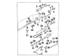
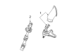
OEM Chevrolet Upper Steering Column Bearing
Upper Tilt Steering Column Bearing- Select Vehicle by Model
- Select Vehicle by VIN
Select Vehicle by Model
orMake
Model
Year
Select Vehicle by VIN
For the most accurate results, select vehicle by your VIN (Vehicle Identification Number).
32 Upper Steering Column Bearings found


Chevrolet Bearing Housing, Upper Part Number: 7819517
$27.29 MSRP: $74.96You Save: $47.67 (64%)Ships in 1-3 Business DaysProduct Specifications- Other Name: Bearing S
- Position: Upper


Chevrolet Bearing Assembly Part Number: 88963617
$33.92 MSRP: $55.88You Save: $21.96 (40%)Ships in 1-3 Business DaysProduct Specifications- Other Name: Bearing, Steering Column; Bearing Kit; Lower Bearing; Lower Bearings
- Replaces: 26056146, 26069723

Chevrolet Bearing Part Number: 26002086
$10.23 MSRP: $19.12You Save: $8.89 (47%)Ships in 1-2 Business DaysProduct Specifications- Other Name: Bearing, Steering Column

Chevrolet Bearing Assembly Part Number: 23275358
$87.52 MSRP: $137.05You Save: $49.53 (37%)Ships in 1-3 Business DaysProduct Specifications- Other Name: Bearing, Steering Column; Steering Shaft; Upper Shaft


Chevrolet Lower Bearing Part Number: 26100500
Product Specifications- Other Name: Bearing, Steering Shaft Lower (W/Adapter)
- Position: Lower
- Replaces: 26077389


Chevrolet Bearing Assembly, Lower Part Number: 26041864
Product Specifications- Other Name: Bearing, Steering Shaft Lower (W/Adapter)
- Position: Lower

Chevrolet Lower Bearing Part Number: 26088662
Product Specifications- Other Name: Bearing, Steering Column
- Position: Lower

Chevrolet Lower Bearing Part Number: 19133753
Product Specifications- Other Name: Bearing, Steering Column; Lower Bearings
- Position: Lower
- Replaced by: 19149963

Chevrolet Upper Bearing Part Number: 20906502
Product Specifications- Other Name: Bearing, Steering Column; Housing Assembly Bearing; Bearing
- Position: Upper
- Replaces: 15216904
Chevrolet Shaft Bearing, Upper Part Number: 7800269
Product Specifications- Other Name: Bearing Assembly-Upper Steering Shaft
- Position: Upper
Chevrolet Bearing Assembly Part Number: 26038070
Product Specifications- Other Name: Bearing, Steering Column; Lower Bearings; Bearing; Bearings

Chevrolet Shaft Bearings, Upper Part Number: 5698407
Product Specifications- Other Name: Bearing, Steering Shaft Upper; Bearings; Bearing, Steering Column
- Position: Upper

Chevrolet Lower Bearing Part Number: 26052238
Product Specifications- Other Name: Bearing, Steering Column; Bearing; Bearings
- Position: Lower

Chevrolet Lower Bearing Part Number: 26025358
Product Specifications- Other Name: Bearing, Steering Column; Shift Tube Bearing; Bearing
- Position: Lower
Chevrolet Bearing Assembly, Lower Part Number: 26086158
Product Specifications- Other Name: Bearing Assembly, Steering Shaft Lower (Includes Adapter); Bearing Kit; Bearing, Steering Column
- Position: Lower

Chevrolet Lower Bearing Part Number: 26081301
Product Specifications- Other Name: Bearing, Steering Column; Bearing
- Position: Lower
- Replaces: 26037395

Chevrolet Lower Bearing Part Number: 26032294
Product Specifications- Other Name: Bearing, Steering Column; Bearing
- Position: Lower

Chevrolet Shaft Bearings Part Number: 26006244
Product Specifications- Other Name: Bearing, Steering Column


Chevrolet Bearing Assembly Part Number: 25754172
Product Specifications- Other Name: Bearing, Steering Column
Chevrolet Bearing Assembly Part Number: 22969824
$68.84 MSRP: $107.83You Save: $38.99 (37%)Product Specifications- Other Name: Bearing, Steering Column
| Page 1 of 2 |Next >
1-20 of 32 Results
Chevrolet Upper Steering Column Bearing
Choose OEM Upper Steering Column Bearing, you're making the optimal decision for superior quality and perfect performance. You can feel confident because each component goes through stringent quality checks. Every part is carefully built to comply with Chevrolet's factory specifications. You'll enjoy a smooth, worry-free installation that fits just right. At ChevyPartsDeal.com, you'll find it easy to get top-quality OEM Chevrolet Upper Steering Column Bearing. You can shop at highly competitive prices and protect your budget. All our genuine Chevrolet parts include a dependable manufacturer's warranty. You'll also appreciate our straightforward return policy and swift delivery services for extra convenience.
Chevrolet Upper Steering Column Bearing continues to make steering smooth and accurate and connects the wheel to the road with certainty. Chevrolet was founded in 1911 and has over 100 years of experience driving the regular person in their everyday mobility, putting muscle and style and practical technology in cars, trucks, and SUVs and making them something people want to drive, whether it be work-based commuting or long-distance hauling, but it continues to drive the same force today with punchy engines, user-friendly infotainment, and consistent innovations like Super Cruise that take the stress out of the driver without the fun, making the driver wish they could drive more. Chevy strikes a balance between cost and durability so that the owners need not sweat every drawback in the road. The badge translates to fast acceleration, heavy load-hauling, spacious interiors, and gizmos that are not glitzy trifles hence both the family shopping and weekend getaways are comfortable. Upper Steering Column Bearing is hidden above the wheel, however, it performs a task each time you flick your wrists into a turn. Within its hard-bearing shell, its rollers are sharpened to near frictionlessness, allowing the shaft to slide rather than grind, maintaining the on-center feel tight, and eliminating the annoying play that can become real danger. Chevy customers experience faster steering, less effort, and feedback since the bearing keeps in line under daily abuse. The Upper Steering Column Bearing also sheds heat, vibration, and moisture easily enough thus the replacement time is increased by far and thick and the wheel remains compliant on challenging roads or muddled freeways. Chevy dependability begins here, at the silent switch point which steers each mile. That obstinate insistence on the drive-line precision explains why Chevrolet continues making its steering components primitive and rough.
Chevrolet Upper Steering Column Bearing Parts and Q&A
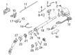
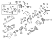
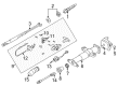
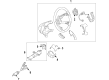
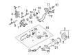
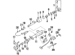
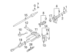
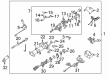
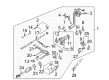
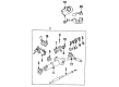
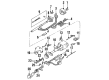
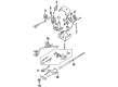
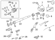
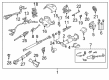
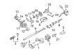
- Q: How to replace the Upper Steering Column Bearing on Chevrolet Tahoe?A:The first step to replace the Steering Shaft upper bearing is to remove the Steering Column. Start by removing the inflatable restraint steering wheel module coil and then proceed to remove the turn signal multifunction switch and ignition lock cylinder case. Crossover the tilt spring while simultaneously removing the automatic transmission control. Before shaft repair proceed with compressor (J 23653-SIR) and adapter (J 42137) to eliminate and dispose of the Steering Shaft lock plate retaining ring. Extract the Steering Column shaft assembly components of Turn Signal Switch cancel cam position plate, Turn Signal Switch cancel cam, steering shaft upper bearing spring, steering shaft upper bearing inner race seat, and Steering Shaft upper bearing inner race. Use remover (J 21854-01) to remove the 2 pivot pins that are found in the Steering Column tilt head assembly. Pull the tilt lever into the Steering Column tilt head assembly before pulling back on the tilt lever to pull the Steering Column tilt head assembly down and away from the Steering Column. Remove the anti-rotation pin (J 42640) and the tilt lever before you pull the Steering Shaft upper bearing from the Steering Column tilt head assembly. Insert the Steering Shaft upper bearing into the Steering Column tilt head assembly after which you should install the Steering Column shaft assembly. The Steering Column tilt head assembly should be maneuvered and pushed to the Steering Column direction which locks the steering wheel lock shoes into position. Place gm p/n 12346293 (Canadian P/N 992723) lubrication onto each pivot pin and firmly insert these pins into the Steering Column tilt head assembly while performing 3 stake points on the Steering Column. Install anti-rotation pin (J 42640) along with the following components onto the Steering Column shaft assembly. First lubricate the Steering Shaft upper bearing inner race with gm p/n 12345718 (Canadian P/N 10953516) before installing the Steering Shaft upper bearing inner race and Steering Shaft upper bearing inner race seat along with Steering Shaft upper bearing spring. Then lubricate the Turn Signal Switch cancel cam with gm p/n 12377900 (Canadian P/N 10953529) before installing the Turn Signal Switch cancel cam and Turn Signal Switch cancel cam position plate. Install the new Steering Shaft lock plate retaining ring onto the Steering Shaft by using compressor (J 23653-SIR) and adapter (J 42137) followed by automatic transmission control assembly then tilt spring and ignition lock cylinder case and turn signal multifunction switch and inflatable restraint steering wheel module coil and Steering Column.
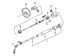
- Q: How to replace the Upper Steering Column Bearing on Chevrolet Colorado?A:The replacement process of an upper steering shaft bearing starts by removing the steering column tilt head housing first. Proceed by removing the steering shaft upper bearing from inside the steering column tilt head housing. When installing insert the new steering shaft upper bearing into the steering column tilt head housing before putting the housing back in place.


Related Chevrolet Parts
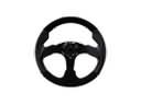 Chevrolet Steering Wheel
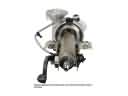 Chevrolet Steering Column
 Chevrolet Tie Rod
 Chevrolet Center Link
 Chevrolet Ignition Lock Cylinder
 Chevrolet Power Steering Reservoir
 Chevrolet Rack And Pinion
 Chevrolet Power Steering Assist Motor
 Chevrolet Radius Heat Shield
 Chevrolet Shift Interlock Solenoid
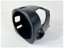 Chevrolet Steering Column Cover
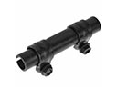 Chevrolet Tie Rod Adjusting Sleeve
Browse Chevrolet Upper Steering Column Bearing by Models
S10 Colorado C10 Tahoe Malibu Camaro Impala Avalanche Silverado 1500 Silverado 2500 HD Caprice Classic Blazer K10 Astro Cavalier Corvette C20 Beretta C1500 C2500 C30 C3500 Celebrity Chevette Corsica Express 1500 Express 2500 Express 3500 G10 G20 G30 K1500 K20 K2500 K30 K3500 K5 Blazer Lumina Monte Carlo P30 S10 Blazer Silverado 2500 Venture Lumina APV Silverado 3500 Suburban 1500 Avalanche 1500 Avalanche 2500 C10 Suburban C1500 Suburban C20 Suburban C2500 Suburban Impala Limited K10 Suburban K1500 Suburban K20 Suburban K2500 Suburban R10 R10 Suburban R1500 Suburban R20 R20 Suburban R2500 R2500 Suburban R30 R3500 Silverado 1500 Classic Silverado 1500 HD Silverado 1500 HD Classic Silverado 2500 HD Classic Silverado 3500 Classic Silverado 3500 HD Suburban 2500 V10 V10 Suburban V1500 Suburban V20 V20 Suburban V2500 Suburban V30 V3500