ChevyParts
My Garage
My Account
Cart
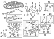
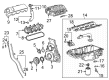
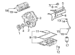
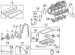
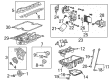
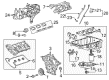
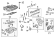
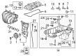
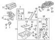
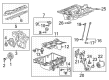
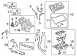
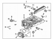
OEM Cadillac Intake Manifold
Engine Intake Manifold- Select Vehicle by Model
- Select Vehicle by VIN
Select Vehicle by Model
orMake
Model
Year
Select Vehicle by VIN
For the most accurate results, select vehicle by your VIN (Vehicle Identification Number).
53 Intake Manifolds found


Cadillac Intake Manifold Part Number: 12699182
$277.94 MSRP: $484.98You Save: $207.04 (43%)Ships in 1-2 Business DaysProduct Specifications- Other Name: Manifold, Engine Fuel Intake Manifold; Intake Plenum; Manifold
- Replaces: 12648915, 12635243


Cadillac Intake Manifold Part Number: 12639087
$124.75 MSRP: $214.25You Save: $89.50 (42%)Ships in 1-2 Business DaysProduct Specifications- Other Name: Manifold, Engine Fuel Intake Manifold; Engine Intake Manifold; Manifold
- Replaced by: 12748172


Cadillac Intake Plenum Part Number: 12555840
$34.48 MSRP: $56.81You Save: $22.33 (40%)Ships in 1-2 Business DaysProduct Specifications- Other Name: Plenum-Intake Manifold; Plenum, Engine Fuel Intake Manifold


Cadillac Intake Plenum Part Number: 12580250
$47.78 MSRP: $78.71You Save: $30.93 (40%)Product Specifications- Other Name: Plenum-Intake Manifold
- Replaces: 12563719

Cadillac Intake Manifold Part Number: 12597600
$132.92 MSRP: $328.50You Save: $195.58 (60%)Ships in 1-2 Business DaysProduct Specifications- Other Name: Manifold, Engine Fuel Intake Manifold; Manifold

Cadillac Intake Manifold Part Number: 12659015
$215.21 MSRP: $531.86You Save: $316.65 (60%)Ships in 1-2 Business DaysProduct Specifications- Other Name: Manifold, Engine Fuel Intake Manifold
- Replaces: 12647953

Cadillac Intake Manifold Part Number: 12674037
$82.58 MSRP: $199.07You Save: $116.49 (59%)Ships in 1-2 Business DaysProduct Specifications- Other Name: Manifold, Engine Fuel Intake Manifold

Cadillac Intake Plenum, Upper Part Number: 55561791
$229.23 MSRP: $456.11You Save: $226.88 (50%)Ships in 1-2 Business DaysProduct Specifications- Other Name: Manifold, Upper Intake; Manifold, Engine Fuel Intake Manifold
- Position: Upper

Cadillac Intake Manifold Part Number: 12631023
$265.02 MSRP: $455.17You Save: $190.15 (42%)Product Specifications- Other Name: Manifold, Engine Fuel Intake Manifold

Cadillac Intake Manifold Part Number: 12642700
$334.04 MSRP: $573.58You Save: $239.54 (42%)Product Specifications- Other Name: Manifold, Engine Fuel Intake Manifold; Intake Plenum
- Replaces: 12635448

Cadillac Intake Manifold Part Number: 19330172
$512.55 MSRP: $872.58You Save: $360.03 (42%)Ships in 1-2 Business DaysProduct Specifications- Other Name: Manifold; Manifold, Engine Fuel Intake Manifold
- Replaces: 12588847, 12564771, 19303933

Cadillac Intake Manifold Part Number: 12706155
$248.38 MSRP: $409.07You Save: $160.69 (40%)Ships in 1-3 Business DaysProduct Specifications- Other Name: Manifold, Engine Fuel Intake Manifold

Cadillac Intake Manifold, Passenger Side Part Number: 12693841
$461.25 MSRP: $759.65You Save: $298.40 (40%)Ships in 1-3 Business DaysProduct Specifications- Other Name: Manifold, Engine Fuel Intake Manifold
- Position: Passenger Side

Cadillac Intake Manifold Part Number: 12713777
$3421.56 MSRP: $5626.00You Save: $2204.44 (40%)Ships in 1-3 Business DaysProduct Specifications- Other Name: Manifold, Engine Fuel Intake Manifold; Supercharger
- Replaces: 12703301

Cadillac Manifold, Engine Fuel Intake Manifold Part Number: 12733472
$5935.10 MSRP: $9776.95You Save: $3841.85 (40%)Product Specifications- Other Name: MANIFOLD ASM-INT
- Replaced by: 12740734


Cadillac Intake Manifold Part Number: 12620308
$223.16 MSRP: $351.12You Save: $127.96 (37%)Product Specifications- Other Name: Manifold, Engine Fuel Intake Manifold; Manifold
- Replaces: 12597598


Cadillac Intake Manifold Part Number: 12580678
$231.11 MSRP: $363.63You Save: $132.52 (37%)Product Specifications- Other Name: Manifold, Engine Fuel Intake Manifold; Manifold


Cadillac Intake Manifold Part Number: 17113541
Product Specifications- Other Name: Manifold Kit, Engine Fuel Intake Manifold; Manifold


Cadillac Intake Manifold, Lower Part Number: 17113201
Product Specifications- Other Name: Manifold Kit, Lower Intake
- Position: Lower


Cadillac Manifold Part Number: 17113697
Product Specifications- Other Name: Manifold, Engine Fuel Intake Manifold; Intake Manifold
- Replaces: 17113546
| Page 1 of 3 |Next >
1-20 of 53 Results
Cadillac Intake Manifold
Choose OEM Intake Manifold, you're making the optimal decision for superior quality and perfect performance. You can feel confident because each component goes through stringent quality checks. Every part is carefully built to comply with Cadillac's factory specifications. You'll enjoy a smooth, worry-free installation that fits just right. At ChevyPartsDeal.com, you'll find it easy to get top-quality OEM Cadillac Intake Manifold. You can shop at highly competitive prices and protect your budget. All our genuine Cadillac parts include a dependable manufacturer's warranty. You'll also appreciate our straightforward return policy and swift delivery services for extra convenience.
Cadillac Intake Manifold directs cool measured air to the cylinders, enhancing throttle response and fuel economy. Cadillac is the brand of big style, comfortable interiors, and a past that dates back to 1902, uniting vintage luxury with the electric future visions such as the hand-crafted Celestiq and its panorama of glass ceiling that screams the future without sacrificing comfort. Cadillac appeals to the consumer who wants a quick, tactile steering wheel, sharp touchscreen screens, and interiors that evoke the feeling of an exclusive club, but prices remain affordable to those who are looking to find high-quality experiences without sacrificing either their budget or individuality. Cadillac does not innovate away either by allowing technology to run the trip, but not to take it over, resulting in voice commands, augmented navigation, and adaptive damping silently performing in the background without the badge breaking its promise of relaxed confidence. Design of the Intake Manifold is important since it pulls the oxygen through the throttle body, evenly divides the flow to all the cylinders, provides the required pressure at high rpm, and in case constructed out of lightweight composite plastic, it loses weight and thus runs cooler giving a cleaner burn and exhaust. Variable length Intake Manifold is an on-fly adjustment of runner distance that allows the intake to run short distances to protect peak horsepower, but lengthens it at cruise to flatten the torque curve and provide smooth acceleration between neighborhood creep and highway blasts without hiccups. Intake Manifold good seals prevent vacuum leakage, maintain fuel economy, and leave the engine computer to its work without obscuring airflow information that determines spark timing and injection.
Cadillac Intake Manifold Parts and Q&A
- Q: How to remove and install the intake manifold in V6 engine on Cadillac Escalade?A:Before the removal of the intake manifold it is required that you pull the cable off the negative terminal of the battery and also lose the fuel system pressure. Subsequently, exclude the air filter housing outlet duct and label, then, disconnect all engine wiring harnesses which affect the intake manifold extraction, by releasing all the harness clip lock, and bundle all strands away from the operation area. Remove the hose connected to the canister purge solenoid if it is already connected, the fuel line connected to the fuel rail and the PCV hose connected to the intake manifold. Then, remove all other electrical connectors or vacuum hoses which are connected to the intake manifold or throttle body. Ease the intake manifold mounting bolts by a quarter turn, and depending on the engine model, they should be easily removable, be very careful not to use any tools to pry between the manifold and the heads as this may cause damage the gasket sealing surfaces. By pulling it over the heads, then unbending any still connected as the intake manifold is lifted off the engine. For Valve Lifter Oil Manifold (VLOM) removal, other components that must be detached include the fuel pump insulator, the fuel rail and injectors, and the balance shaft sprocket; the VLOM assembly mounting bolts are then removed and the gasket, in case it is still serviceable, should be saved. On mating, the places where the cylinder heads, block and the manifold sit should be absolutely clean: rid of all gasket debris by gentle scraping off at most. Wipe the ribs of the new gasket and place it over the cylinder block, if the VLOM has been removed, replace it and fasten the bolts to the recommended torque. Place the new gaskets in the appropriate position on the intake manifold so that they fit into place and cover the intake port holes; then, with equal care, position and fit the manifold in the space provided. Screw in the bolts and fasten them according to the sequence and torque value but with great care to avoid tightness that will lead to gasket leakage. Last of it, the rest of the installation if done in the reverse manner to removal and once the engine has been started, look out for vacuum leaks at the joints of the intake manifold.
- Q: How to remove and install the intake manifold in 2.8L,3.0L,3.6L V6 engine on Cadillac CTS?A:Before the intake manifold can be removed, one has to release the fuel system pressure and join the negative terminal of the battery. Pull down the suspension crossbrace off from the top of the front struts and the covers of the engine. For the 2005 through 2011 models with 2.6L and 3.6L engines first remove the wiring from the MAF sensor as well as the air intake duct, next disconnect the throttle control motor wiring connector as well as the PCV pipe. At the rear of the engine remove the wiring connection from the barometric pressure sensor, fuel injector harness, EVAP purge solenoid and the variable intake manifold control valve motor bolts; manifold brace bolts, the plenum bolts. Remove the plenum from the intake manifold disengaging all the remaining connections and detach the fuel line connected to the rear end of the fuel rail. Take out intake manifold bolts connect to the cylinder heads and lift of the intake manifold from the engine. On 3.0L engines remove brake booster vacuum hose, the PCV valve, the EVAP hose and all electrical connections to the intake manifold before removing the assembly. In 2012 and later models, remove the PCV tube and EVAP hose, the fuel rail shield, and any electrical connectors that you can see before popping up the intake manifold and its gasket. When tightening let the mating faces be clean, when replacing gaskets, eliminate the old gasket material gently and replace with fresh gaskets in the right manner. Then place the manifold in correct position, add the thread locking compound to the bolt and then tighten the bolts in correct pattern and to the torque value. Last but not the least; check the coolant level, engage the engine and look for the vacuum leaks at the joints of the intake manifold.


Related Cadillac Parts
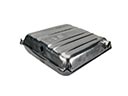 Cadillac Fuel Tank
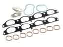 Cadillac Intake Manifold Gasket
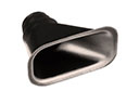 Cadillac Air Duct
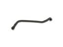 Cadillac Crankcase Breather Hose
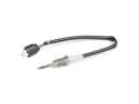 Cadillac Exhaust Gas Temperature Sensor
 Cadillac Fuel Pump Driver Module
 Cadillac Fuel Pump Gasket
 Cadillac Fuel Water Separator Filter
 Cadillac Idle Control Valve
 Cadillac PCV Valve Hose
 Cadillac Throttle Body Gasket
 Cadillac Turbocharger