ChevyParts
My Garage
My Account
Cart
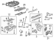
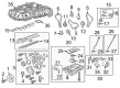
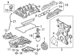
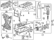
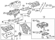
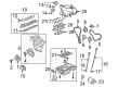
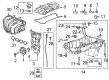
OEM Chevrolet Equinox Intake Manifold
Engine Intake Manifold- Select Vehicle by Model
- Select Vehicle by VIN
Select Vehicle by Model
orMake
Model
Year
Select Vehicle by VIN
For the most accurate results, select vehicle by your VIN (Vehicle Identification Number).
14 Intake Manifolds found


Chevrolet Equinox Intake Manifold Part Number: 12637620
$94.22 MSRP: $164.41You Save: $70.19 (43%)


Chevrolet Equinox Intake Manifold Part Number: 12699182
$277.94 MSRP: $484.98You Save: $207.04 (43%)Ships in 1-2 Business Days
Chevrolet Equinox Intake Manifold Part Number: 12600281
$240.67 MSRP: $727.26You Save: $486.59 (67%)Ships in 1-2 Business Days
Chevrolet Equinox Intake Manifold Part Number: 25204428
$119.28 MSRP: $196.49You Save: $77.21 (40%)Ships in 1-3 Business Days
Chevrolet Equinox Intake Manifold Part Number: 12683666
$192.71 MSRP: $317.32You Save: $124.61 (40%)Ships in 1-3 Business Days
Chevrolet Equinox Intake Manifold Part Number: 12646130
$191.76 MSRP: $334.56You Save: $142.80 (43%)Ships in 1-2 Business Days
Chevrolet Equinox Intake Manifold, Lower Part Number: 12611205
$403.91 MSRP: $641.01You Save: $237.10 (37%)Ships in 1-3 Business Days
Chevrolet Equinox Intake Manifold Part Number: 12611155
$370.63 MSRP: $588.47You Save: $217.84 (38%)Ships in 1-2 Business Days
Chevrolet Equinox Intake Manifold Part Number: 12634205

Chevrolet Equinox Intake Manifold Part Number: 19371505

Chevrolet Equinox Intake Manifold Part Number: 12597697
Chevrolet Equinox Intake Manifold Part Number: 12591901

Chevrolet Equinox Intake Manifold Part Number: 12591211

Chevrolet Equinox Intake Manifold Part Number: 55505747
$355.45 MSRP: $559.28You Save: $203.83 (37%)
Chevrolet Equinox Intake Manifold
Want to cut long-term maintenance and repair costs? Choose OEM Intake Manifold. Those parts deliver top durability you can trust. On our site, you'll find a huge catalog of genuine Chevrolet Equinox parts. Prices are unbeatable, so you can keep more in your pocket. Every OEM Chevrolet Equinox Intake Manifold includes a manufacturer's warranty. You can also get an easy return policy that keeps buying risk free. Fast delivery, get your car on the road quickly. It's simple to search, compare, and order. Stop guessing about quality or fit. Order today and save with parts that last.
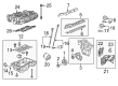
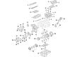
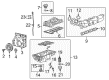
The Intake Manifold of Chevrolet Equinox vehicles is responsible for the distribution of the air or air/fuel mixture to the respective cylinders affecting the performance and the power of the vehicle. This it does with the help of number of designs such as VLIM (Variable Length Intake Manifold) that controls airflow and brings about efficiency through Air Ramming, Venturi Tube and Helmholtz resonance. With time, Chevrolets used various materials in the manufacturing process and the older models were cast iron and aluminum whereas the current models use more composite plastics because they are light and they also have tendencies of reducing heat. This promotes a shift which also helps in creating cooler layer of air with better conditions for combustion. The Intake Manifold construction has undergone changes over the years whereby it is equipped with features such as temperature and airflow sensors to improve on the performance of the engine.
Chevrolet Equinox Intake Manifold Parts and Q&A
- Q: How to replace the upper intake manifold on Chevrolet Equinox?A:Begin upper Intake Manifold replacement by removing the fuel injector sight shield then disconnecting the Brake Booster Vacuum Hose and releasing the clamp before separating the hose from the Intake Manifold. Disconnect the left side Spark Plug Wires from their retainers and Spark Plugs before you remove the Ignition Control Module bracket while keeping Ignition Control Module and wires connected. Position the bracket away from the work area. Maintain heat while disconnecting the heater outlet pipe from the Throttle Body. Remove the lower nut from the upper Intake Manifold followed by both upper nuts and bolt from the Throttle Body until positioning the heater outlet pipe in place where heater hoses stay connected. Extract both the exhaust gas recirculation (EGR) tube and the positive crankcase ventilation (PCV) foul air tubing. Without completely removing the generator attachment bolt near the Intake Manifold start loosening it then remove the generator brace nut and brace. The maintenance procedure requires removal of upper Intake Manifold bolts (4, 5) and Spark Plug wire retainer and upper Intake Manifold together with upper Intake Manifold gaskets . To replace the upper Intake Manifold you must also dismantle the manifold absolute pressure (MAP) sensor alongside the EGR Valve and evaporative emissions (EVAP) purge solenoid valve and Throttle Body and the fuel injector sight shield studs. During installation clamp upper Intake Manifold gaskets securely onto the lower Intake Manifold using fir tree retainers before mounting the upper Intake Manifold together with the Spark Plug wire retainer . Apply threadlock gm p/n 12345382 (Canadian P/N 10953489) to each upper Intake Manifold bolt thread before tightening the bolts (4, 5) to 25 nm (18 ft. Lbs.). The fuel injector sight shield studs need installation followed by the Throttle Body and evap purge solenoid valve, egr valve and MAP Sensor. After applying threadlocker gm p/n12345382 (Canadian P/N10953489) to bolts, install the generator brace and tighten the generator brace nut to 25 nm (18 ft. Lbs.). Fully insert and tighten the generator attachment bolt nearest to the Intake Manifold to 25 nm (18 ft. Lbs.). Secure the pcv foul air hose together with the egr pipe while positioning the heater outlet pipe to fit both Throttle Body and upper Intake Manifold. Install both heater outlet pipe nuts onto the Throttle Body and tighten them to 10 nm (89 inch lbs.), followed by installing the heater outlet pipe bolt to the Throttle Body with a torque of 10 nm (89 inch lbs.) to attach the upper Intake Manifold nut tightly to 25 nm (18 ft. Lbs.). The repair process includes installing the air cleaner intake duct followed by the Ignition Control Module bracket, left side Spark Plug wire connection to spark plugs and respective retainers and Brake Booster Vacuum Hose connection to the Intake Manifold. Clamp installation should occur before reinstallation of the fuel injector sight shield.

Related Chevrolet Equinox Parts
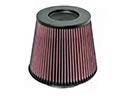 Chevrolet Equinox Air Filter
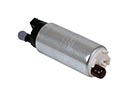 Chevrolet Equinox Fuel Pump
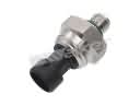 Chevrolet Equinox Fuel Pressure Sensor
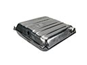 Chevrolet Equinox Fuel Tank
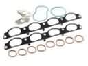 Chevrolet Equinox Intake Manifold Gasket
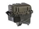 Chevrolet Equinox Air Filter Box
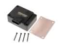 Chevrolet Equinox Fuel Pump Driver Module
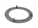 Chevrolet Equinox Fuel Pump Gasket
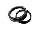 Chevrolet Equinox Fuel Pump Seal
 Chevrolet Equinox Fuel Tank Filler Neck
 Chevrolet Equinox Fuel Tank Lock Ring
 Chevrolet Equinox Vapor Pressure Sensor