ChevyParts
My Garage
My Account
Cart
OEM Chevrolet HHR Fuel Rail
Engine Fuel Rail- Select Vehicle by Model
- Select Vehicle by VIN
Select Vehicle by Model
orMake
Model
Year
Select Vehicle by VIN
For the most accurate results, select vehicle by your VIN (Vehicle Identification Number).
2 Fuel Rails found


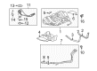
Chevrolet HHR Fuel Rail, Green Line Part Number: 12602482
$172.14 MSRP: $349.62You Save: $177.48 (51%)Ships in 1-2 Business Days
Chevrolet HHR Fuel Rail Part Number: 12615400
$410.92 MSRP: $771.68You Save: $360.76 (47%)
Chevrolet HHR Fuel Rail
Want to cut long-term maintenance and repair costs? Choose OEM Fuel Rail. Those parts deliver top durability you can trust. On our site, you'll find a huge catalog of genuine Chevrolet HHR parts. Prices are unbeatable, so you can keep more in your pocket. Every OEM Chevrolet HHR Fuel Rail includes a manufacturer's warranty. You can also get an easy return policy that keeps buying risk free. Fast delivery, get your car on the road quickly. It's simple to search, compare, and order. Stop guessing about quality or fit. Order today and save with parts that last.
Chevrolet HHR Fuel Rail Parts and Q&A
- Q: How to replace the Fuel Injection Fuel Rail Assembly on Chevrolet HHR?A:The first step is to reduce fuel system pressure that requires ch 48027 if the system includes it or no tool for systems without ch 48027. Remove the air cleaner assembly followed by disconnecting three components from their locations: the fuel feed quick connect fitting from the Fuel Rail and the evaporative emission (EVAP) purge tube from the Intake Manifold and the Fuel Injector harness electrical connector. The electrical connection for the manifold absolute pressure (MAP) sensor also needs removal. The Intake Manifold receives the removal of Fuel Injector harness electrical connector clips (4 and 5) ahead of the Fuel Rail stud removal. Dull movements are necessary during Fuel Rail assembly removal because damage can occur to the Fuel Injector electrical connector terminals and spray tips. You should pull the Fuel Rail in an upward and backward direction to remove fuel injectors from the cylinder head ports before taking out the Fuel Rail assembly including the fuel injectors. New lower o-rings must be installed for recycled fuel injectors ahead of lubricating the injector tip o-rings just before insertion into the Intake Manifold. Position the fuel injectors with their downward sides facing and then insert them into the cylinder head ports by gentle pressure. Secure the Fuel Rail bolts at 10 n.m (89 lb in). The Fuel Injector harness electrical connector and map sensor electrical connector together with clips (4 and 5) must be reattached to the Intake Manifold. Before reinstalling the air cleaner assembly you must route both the evap purge tube to the Intake Manifold alongside the fuel feed line quick connect fitting to the Fuel Rail and lastly connect the negative Battery Cable. To check for leaks turn on the ignition while the engine remains off for two seconds before turning the ignition off for ten seconds and checking again for any fuel leaks by turning the ignition back on.

Related Chevrolet HHR Parts
 Chevrolet HHR Air Filter
 Chevrolet HHR Air Hose
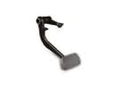 Chevrolet HHR Brake Pedal
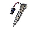 Chevrolet HHR Fuel Injector
 Chevrolet HHR Fuel Injector O-Rings
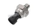 Chevrolet HHR Fuel Pressure Sensor
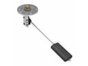 Chevrolet HHR Fuel Sending Unit
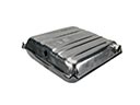 Chevrolet HHR Fuel Tank
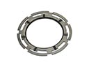 Chevrolet HHR Fuel Tank Lock Ring
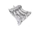 Chevrolet HHR Intake Manifold
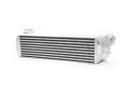 Chevrolet HHR Intercooler
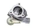 Chevrolet HHR Turbocharger