ChevyParts
My Garage
My Account
Cart
OEM 2007 Chevrolet HHR Control Arm Bushing
Suspension Arm Bushing- Select Vehicle by Model
- Select Vehicle by VIN
Select Vehicle by Model
orMake
Model
Year
Select Vehicle by VIN
For the most accurate results, select vehicle by your VIN (Vehicle Identification Number).
1 Control Arm Bushing found


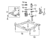
2007 Chevrolet HHR Lower Control Arm Bushing Part Number: 15232501
$35.00 MSRP: $57.64You Save: $22.64 (40%)Ships in 1-2 Business DaysProduct Specifications- Other Name: Bushing, Steering Knuckle Lower Control Arm; Suspension Control Arm Bushing; Control Arm Bushing; Axle Pivot Bushing; Lower Control Arm Rear Bushing
- Position: Lower
- Replaces: 22700089
- Item Weight: 0.80 Pounds
- Item Dimensions: 3.0 x 3.0 x 2.3 inches
- Condition: New
- Fitment Type: Direct Replacement
- SKU: 15232501
- Warranty: This genuine part is guaranteed by GM's factory warranty.
2007 Chevrolet HHR Control Arm Bushing
With a comprehensive array of OEM 2007 Chevrolet HHR Control Arm Bushing, from fuel pumps to door handles, our website is a one-stop-shop for your needs. All our genuine 2007 Chevrolet HHR Control Arm Bushing are backed by the manufacturer's warranty and are offered at competitive prices in the market. Rest assured, you can shop with complete confidence.
2007 Chevrolet HHR Control Arm Bushing Parts and Q&A
- Q: How to replace the control arm bushing in the rear suspension on 2007 Chevrolet HHR?A: To replace the control arm bush in rear suspension, one will raise and support the vehicle and remove the rear wheels and position two screw type jack stands under each end of the rear axle. Perform the rear brake hose brackets unclipping from the body so as to free the lines, and lower the shock bolts, db with care to avoid the brake pipes from getting kinked as the axle gets lowered. Now drop the jacks to take off the Coil Springs, temporarily constrain the lower bolts on the shocks to lift the axle, and then remove the bushing bracket from the body bolts at both sides of the rear axle. Apply the jack stands to load the rear part of the axle till bushing brackets are ready to turn distant from the body, and unscrew the axle through bolts of bushings together with bushing brackets, and remember observing the depth and orientation of an old bushing. Use the j 44570 bushing remover/installer kit to properly install the j 44570-1 with the lip between the axle sleeve and bushing flange with the likely use of a hammer to seat the tool completely. Put in j 44570-3 through the j 44570-1 and the axle bushing, and then put the washer and nut on by hand, and tighten until it is tight. Hammer the bushing out of the axle sleeve, but using a toolbox, disassemble after pulling out the bushing. For installation, push the new bushings into the axle sleeve in the same orientation as was observed during removal and make sure rubber end faces inboard and the largest void aligns with wheel hub center. Put the j 44570-1 on the properly oriented bushing and insert j 44570-3 into the j 44570-1 and axle bushing and then install the j 44570-2 on the bearing, washer and nut. Pull the bushing into the axle sleeve by gripping only the hex end of the threaded shaft while spinning the nut, and disassemble and remove the bushing installation tool. Mount axle brackets on axle bushings with alignment slot on outboard side. Bolt head on axle bushing through bolts to be inboard. Loosely mount the bushing bolts, the park brake cable brackets, and nuts, lower the rear of the axle until the bushing brackets meet the body. Hand tighten the axle bracket to body bolts just enough to take the brackets flush to the body, and the axle through bolts, tighten at the correct trim height before fastening the axle bracket to body bolts. Raise the axle to the correct trim height specification, tighten the axle bushing through bolts to 90 n.m (66 lb ft) +60 degrees, insert two 12 mm diameter pins through axle into the underbody, and do axle bracket left and right side axle bracket bolts. Tighten all bracket to body bolts to 90 n.m (66 lb ft) +30 degrees, then upper area for the axle is supported by jack stands, remove the lower jaws, then the shock bolt, the lower jacks to have the Coil Springs have the colored tag face the rear of the vehicle. Lift the jacks up as far as the springs are compressed a little to put the lower shock bolts in and tighten it to 125 n.m (92 lb ft), and take away the jack stands and move the rear brake hose brackets to the body and put the brake hose bracket attaching nuts on and install the rear wheels and then drop the vehicle.
Related 2007 Chevrolet HHR Parts
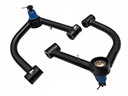 2007 Chevrolet HHR Control Arm
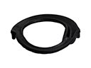 2007 Chevrolet HHR Coil Spring Insulator
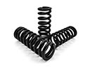 2007 Chevrolet HHR Coil Springs
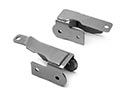 2007 Chevrolet HHR Control Arm Bracket
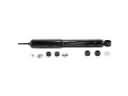 2007 Chevrolet HHR Shock Absorber
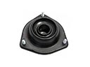 2007 Chevrolet HHR Shock And Strut Mount
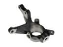 2007 Chevrolet HHR Steering Knuckle
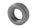 2007 Chevrolet HHR Strut Bearing
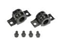 2007 Chevrolet HHR Sway Bar Bracket
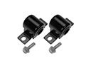 2007 Chevrolet HHR Sway Bar Bushing
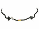 2007 Chevrolet HHR Sway Bar Kit
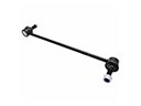 2007 Chevrolet HHR Sway Bar Link