ChevyParts
My Garage
My Account
Cart
OEM GMC Savana 3500 Ball Joint
Control Arm Joint- Select Vehicle by Model
- Select Vehicle by VIN
Select Vehicle by Model
orMake
Model
Year
Select Vehicle by VIN
For the most accurate results, select vehicle by your VIN (Vehicle Identification Number).
5 Ball Joints found


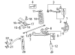
GMC Savana 3500 Lower Ball Joint, Front Part Number: 12475478
$129.19 MSRP: $161.18You Save: $31.99 (20%)Ships in 1-2 Business Days
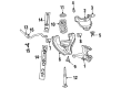
GMC Savana 3500 Lower Ball Joint, Front Part Number: 19416896
$88.06 MSRP: $145.05You Save: $56.99 (40%)Ships in 1-2 Business Days
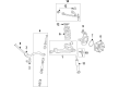
GMC Savana 3500 Lower Ball Joint, Front Part Number: 19210782
$47.17 MSRP: $117.97You Save: $70.80 (61%)Ships in 1-2 Business Days

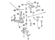
GMC Savana 3500 Upper Ball Joint Part Number: 19146901
GMC Savana 3500 Upper Ball Joint, Front Part Number: 19416903
GMC Savana 3500 Ball Joint
Want to cut long-term maintenance and repair costs? Choose OEM Ball Joint. Those parts deliver top durability you can trust. On our site, you'll find a huge catalog of genuine GMC Savana 3500 parts. Prices are unbeatable, so you can keep more in your pocket. Every OEM GMC Savana 3500 Ball Joint includes a manufacturer's warranty. You can also get an easy return policy that keeps buying risk free. Fast delivery, get your car on the road quickly. It's simple to search, compare, and order. Stop guessing about quality or fit. Order today and save with parts that last.
GMC Savana 3500 Ball Joint Parts and Q&A
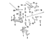
- Q: How to replace the lower control arm ball joint on GMC Savana 3500?A:Before you start replacing the lower Control Arm Ball Joint you need to lift and stabilize the vehicle before you take off its tire and wheel. Set the lower Control Arm aside by placing it into a mechanical screw clamp device. Apply chisel pressure to detach the 4 locking crimps from the Ball Joint component before pressing the joint off the lower Control Arm. Insert the new Ball Joint by pressing it through the outer flange. Set the lower Control Arm in the bench vice before punching four crimps on the Ball Joint from the replaced part. Install the lower Control Arm before the tire wheel and lower the vehicle to verify alignment.
- Q: What tools are required to service and repair the ball joint with heavy-duty suspension on GMC Savana 3500?A:You will require the Ball Joint separator tool with item number j23742 to service and fix the heavy-duty suspension Ball Joint. Use safety stands to raise the vehicle before the floor jack positions under the lower Control Arm during installation to avoid dangers. Place the floor jack under the lower Control Arm to support it during work before taking off the tire and wheel. Secure the brake caliper using wire as a support. You should first extract the brake caliper right after taking the wheel speed sensor harness bracket bolts and nut from their positions on top of the upper Control Arm. Start by center punching the rivets where the Ball Joint connects to the Control Arm. After that, drill 6.35 mm (1/4 inch) deep holes at the center of each rivet using a 3.175 mm (1/8 inch) drill. Keep drilling and remove the rivet heads with a 12.7 mm (1/2 inch) drill. Press the rivets out with a small pin punch and take away both the cotter pin and nut afterward. The Ball Joint separator tool j23742 lets you disconnect the Ball Joint from the Steering Knuckle. Next remove the separator and grasp the knuckle stud to free the Ball Joint. Fit the new upper Ball Joint to the upper Control Arm then connect its four bolts and nuts and tighten the upper Ball Joint retaining nuts to 24 nm (18 ft. Lbs.). Fasten the upper Ball Joint to the Steering Knuckle by torquing the nut to 100 nm (74 ft-lbs). Thread a new cotter pin into the slot of the nut while placing its end through the stud until it reaches the correct alignment. Bend the cotter pin as a lock system for the Ball Joint and add the grease fitting to apply lubricant when available. Fasten the sleeve that holds the wheel sensor wiring harness at the Control Arm by threading the retaining bolt to 17 nm (13 ft. Lbs.). Put back the front brake caliper and mount the tire and wheel system. Last, test all suspension components for proper clearance and take the safety stands off to let the vehicle down before examining front wheel alignment.


Related GMC Savana 3500 Parts
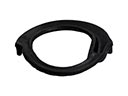 GMC Savana 3500 Coil Spring Insulator
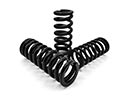 GMC Savana 3500 Coil Springs
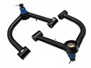 GMC Savana 3500 Control Arm
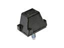 GMC Savana 3500 Control Arm Bumper
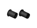 GMC Savana 3500 Control Arm Bushing
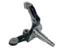 GMC Savana 3500 Spindle
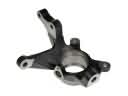 GMC Savana 3500 Steering Knuckle
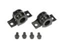 GMC Savana 3500 Sway Bar Bracket
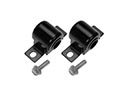 GMC Savana 3500 Sway Bar Bushing
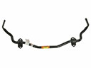 GMC Savana 3500 Sway Bar Kit
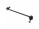 GMC Savana 3500 Sway Bar Link
 GMC Savana 3500 Torsion Bar