ChevyParts
My Garage
My Account
Cart
OEM GMC Jimmy Tie Rod End
Steering Rod End- Select Vehicle by Model
- Select Vehicle by VIN
Select Vehicle by Model
orMake
Model
Year
Select Vehicle by VIN
For the most accurate results, select vehicle by your VIN (Vehicle Identification Number).
5 Tie Rod Ends found

GMC Jimmy Outer Tie Rod Part Number: 26051689
$129.62 MSRP: $213.53You Save: $83.91 (40%)Ships in 1-2 Business Days
GMC Jimmy Outer Tie Rod Part Number: 26041018
$24.65 MSRP: $49.51You Save: $24.86 (51%)
GMC Jimmy Outer Tie Rod Part Number: 26029999
$21.13 MSRP: $42.44You Save: $21.31 (51%)GMC Jimmy Outer Tie Rod Part Number: 26054936

GMC Jimmy Outer Tie Rod Part Number: 12471300
GMC Jimmy Tie Rod End
Want to cut long-term maintenance and repair costs? Choose OEM Tie Rod End. Those parts deliver top durability you can trust. On our site, you'll find a huge catalog of genuine GMC Jimmy parts. Prices are unbeatable, so you can keep more in your pocket. Every OEM GMC Jimmy Tie Rod End includes a manufacturer's warranty. You can also get an easy return policy that keeps buying risk free. Fast delivery, get your car on the road quickly. It's simple to search, compare, and order. Stop guessing about quality or fit. Order today and save with parts that last.
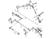
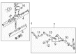
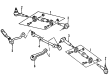
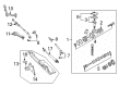
GMC Jimmy Tie Rod End is an essential part that is used to link the GMC Jimmy vehicle's steering rack to its steering knuckles with a view of delivering accuracy besides stability. Being one of the most trusted and recognized parts in automotive sectors, the Tie Rod End is involved in the steering system, which improves the vehicle's operation and security during its operation. This reliable gear is made to fit different GMC Jimmy models manufactured between 1970 and 2002 with an accent on improved performance on both asphalt and rough terrains, which makes the part highly valued in the community of car lovers as well as ordinary drivers. The GMC Jimmy Tie Rod End can withstand considerable usage due to its tough make and lasts long giving a precise turn on the wheel. The design feature lets it achieve correct orientation that has a direct relation to the car's steadiness and tyre usage, making the driving mode safer. Also, the equipped Tie Rod End that serves as a shock-absorber of vibrations improves comfort during the trip which also singles out the product in the automotive market. Being associated with the GMC brand name, the GMC Jimmy Tie Rod End also claims its tradition of delivering quality and performance, thus making the GMC Jimmy a perfect car for those who would love both, adventures as well comfort. From the city roads to the tough tracks and trails for the GMC Jimmy Tie Rod End is an important component of the steering system of the SUV and endorses the GMC Jimmy yet again.
GMC Jimmy Tie Rod End Parts and Q&A
- Q: How to service and repair the tie rod end on GMC Jimmy?A:To service and repair Tie Rod end raise and support the vehicle suitably with safety stands. Start with the cotter pin removal of the outer Tie Rod ball stud nut, followed by the same of the outer Tie Rod ball stud nut and inner Tie Rod ball stud nut. Steer clear of disconnecting a steering linkage joint by driving a wedge between it and the attached part to prevent seal from being damaged. Separate all tie rods and Ball Joints by using the steering linkage and Tie Rod puller (J 24319-B) to remove the outer Tie Rod ball stud from the Steering Knuckle and the Tie Rod puller (J 6627-A) to the inner Tie Rod ball stud from the relay rod. It is only necessary to loosen the clamp bolts and unscrewness the assemblies to remove the Tie Rod ends from the adjuster tube. Check for damage or severe wear on the tie rods end, seals, threads, and adjuster tube. Measure and install a ball stud maximum of 65mm (2 1/2 in.) antagonist platform ball stud. If the Tie Rod ends were removed, also lubricate them with chassis lubricant and make sure the number of threads each inner and the outer Tie Rod ends is equal in three threads respectively. Connect the end of the Tie Rod to the adjuster tube, position the inner Tie Rod ball stud to the relay rod and ensure that the seal is on the former, seat the taper with the help of the steering linkage installer (12 mm) (J 29193) or steering linkage installer (14 mm) (J 29194) and tighten up to 54 nm (40 ft. Lbs.). Scrub off the installer and apply a new nut to the inner Tie Rod ball stud and tighten to 47 nm (35 ft. Lbs.). Next, install the out t.ie rod ball stud to the Steering Knuckle, with seal on the stud and seat the taper again using either j 29193 or j 29194, apply 54 nm (40 ft. Lbs.). Remove the installer and install nut onto the outer Tie Rod ball stud and tighten to 53 nm (39 ft. Lbs.) make sure that the nut acts forward to align to the hole of cotter pin. Place a new cotter pin to the outer rod nut of the Tie Rod and open the ends of the cotter pin. Lower the vehicle and adjust tail end towards. Place the two clamps between the locating dimples at each end of the adjuster tube while ensuring that the clamp slot is not aligned with the adjuster tube slot and continue holding the position of each Tie Rod end as the clamps are being tightened to allow free movement in the each joint. Lastly, install the adjuster tube clamp bolts and tighten them up to 21 nm (16 ft. Lbs).

Related GMC Jimmy Parts
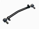 GMC Jimmy Drag Link
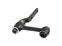 GMC Jimmy Idler Arm
 GMC Jimmy Ignition Lock Assembly
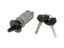 GMC Jimmy Ignition Lock Cylinder
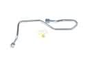 GMC Jimmy Power Steering Hose
 GMC Jimmy Power Steering Pump
 GMC Jimmy Rack And Pinion
 GMC Jimmy Steering Column Cover
 GMC Jimmy Steering Column Seal
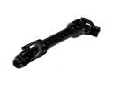 GMC Jimmy Steering Shaft
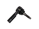 GMC Jimmy Tie Rod
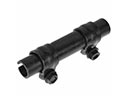 GMC Jimmy Tie Rod Adjusting Sleeve