ChevyParts
My Garage
My Account
Cart
OEM Chevrolet Tracker Intake Manifold
Engine Intake Manifold- Select Vehicle by Model
- Select Vehicle by VIN
Select Vehicle by Model
orMake
Model
Year
Select Vehicle by VIN
For the most accurate results, select vehicle by your VIN (Vehicle Identification Number).
5 Intake Manifolds found

Chevrolet Tracker Intake Manifold Part Number: 91176128

Chevrolet Tracker Intake Manifold Part Number: 91176126

Chevrolet Tracker Intake Manifold Part Number: 91176127
Chevrolet Tracker Intake Manifold Part Number: 91175202
Chevrolet Tracker Intake Manifold Part Number: 91175111
Chevrolet Tracker Intake Manifold
Want to cut long-term maintenance and repair costs? Choose OEM Intake Manifold. Those parts deliver top durability you can trust. On our site, you'll find a huge catalog of genuine Chevrolet Tracker parts. Prices are unbeatable, so you can keep more in your pocket. Every OEM Chevrolet Tracker Intake Manifold includes a manufacturer's warranty. You can also get an easy return policy that keeps buying risk free. Fast delivery, get your car on the road quickly. It's simple to search, compare, and order. Stop guessing about quality or fit. Order today and save with parts that last.
Intake Manifold found on Chevrolet Tracker is as integral part of the car's engine responsible for supplying air or a mixture of air and fuel to the car's cylinder with the aim of getting the maximum power from the engine. Usually, they are made of plastic for lesser weight and for heat dissipation and the shape of the intake manifold is designed in such a way that its runners are balanced for proper air mixture for combustion. Some manifolds have coolant passages and sensors to improve the function of the engine, while ones deliver more horsepower and torque due to the better distribution of air/fuel mixtures. Additional adaptations include variable length intakes that can control the speed as well as pressure of the airflow to match the load engine conditions hence creating highly powerful and fuel-efficient engines.
Chevrolet Tracker Intake Manifold Parts and Q&A
- Q: How to service and repair the intake manifold on Chevrolet Tracker?A:Service and repair of the Intake Manifold starts with removing the fuel tank filler cap to reduce fuel vapor pressure before reinstalling it. Remove fuel pressure while you disconnect the negative cable from the battery. Remove the vehicle's cooling system liquid while also detaching both the mass air flow (MAF) sensor and intake air temperature (IAT) sensor. First disconnect the air cleaner assembly electrical harness clamps while detaching the air intake hose that connects to the Throttle Body. The repair requires detachment of the accelerator cable from its bracket location and its position on the bellcrank portion of the Throttle Body. The service requires removal of the throttle position (TP) sensor along with the idle air control (IAC) valve and engine coolant temperature (ECT) sensor and evaporative emission canister purge valve. Squeeze together the bracket and valve assembly by removing the evap canister purge valve vacuum hose and its bracket bolt. Then pull out the bracket and valve assembly. The coolant hose removal from the Throttle Body requires disconnecting of the exhaust gas recirculation (EGR) connector and the manifold absolute pressure (MAP) sensor connector and engine ground wire from the Intake Manifold. Disconnect the brake booster supply hose from its position on the Intake Manifold by placing a shop rag under the hose to collect any fuel that may leak from disrupted fuel lines. Disrupt the fuel lines connecting both inlet and return before you remove the upper Radiator Hose from its Thermostat Housing placement. The procedure requires removal of the upper generator mounting bracket as well as the lower Intake Manifold support bracket from the Intake Manifold. Take out the upper front Intake Manifold support bracket along with the upper rear Intake Manifold support bracket from the Intake Manifold. Extract both the crankcase vent hose and the pcv hose from their positions on the PCV Valve. Start by disconnecting the fuel injector 6-way connector at the rear of the Intake Manifold before you remove the EGR Valve along with all eight nuts, three bolts, and the Intake Manifold and gasket binding the Cylinder Head. Transfer the ect sensor, ect sensor sending unit, throttle body, Fuel Rail, fuel injector harness, map sensor, EGR Tube and accelerator cable bracket according to required steps. During assembly place the EGR Valve and ect sensor and ect sensor sending unit and Throttle Body and Fuel Rail and fuel injector harness and map sensor and EGR Tube and accelerator cable bracket onto the Intake Manifold. Double check all connections before using new Intake Manifold gaskets to mount the Intake Manifold to the Cylinder Head using 8 nuts and 3 bolts torque to 23 nm (17 ft. Lbs.). The upper rear Intake Manifold support bracket gets installed through two bolts that require 50 nm (37 ft. Lbs. Of torque), while the upper front Intake Manifold support bracket needs the same torque using 2 bolts. Affix the crankcase vent hose and pcv hose onto the pv valve. The 6-way connector of the fuel injector should be connected at the Intake Manifold rear while installing the lower Intake Manifold support bracket through 2 bolts that need tightening at 50 nm (37 ft. Lbs.). Failure to tighten the two upper bracket bolts to 50 nm (37 ft. Lbs.) can lead to exceeding the upper torque limit. Adjust the generator drive belt tension after bolting up the bracket. Reinstall the evap canister followed by connecting the upper Radiator Hose onto the Thermostat Housing . Affix fuel inlet hose and return hose to their positioning on the fuel line union. The service must begin with reconnecting the egr connector and map sensor connector and engine ground wire to the Intake Manifold followed by reconnecting the brake booster supply hose. After installing all components the evap canister purge valve vacuum hose must be placed before continuing with the procedure. First connect the Throttle Body coolant hose before installing both the accelerator cable and Throttle Body bellcrank to its respective mounting positions. Make all necessary adjustments during installation. When finished install the electrical harness clamps onto the air cleaner assembly while also connecting the iat sensor and maf sensor to the Throttle Body. Then perform cooling system refilling as needed before tightening the negative Battery Cable bolt to 15 nm (11 ft. Lbs.).
- Q: How to remove and install the intake manifold on Chevrolet Tracker?A:Starting the Intake Manifold removal demands disconnecting the negative Battery Cable and releasing the fuel pressure. Remove the air cleaner hose while also draining out the engine coolant. After disconnecting the accelerator cable bracket bolt from the Intake Manifold you must detach both Throttle Body bellcrank cables. The mechanic must disconnect three sensors - fuel injector harness, MAP Sensor and Throttle Position Sensors - along with three more components - iac valve, evap canister purge valve and EGR Valve. First disconnect ground wires with bolts from the Intake Manifold before gently freeing the evap canister purge hose and vacuum line from Intake Manifold components. Detach the bolt securing the evap canister purge valve then remove the Throttle Body and Intake Manifold coolant hoses (4,5) while removing the evap canister purge valve. Separate the two bolts holding the coolant line behind the Intake Manifold while also removing the brake booster hose and pcv hose and breather hose and fuel pressure regulator vacuum hose. Remove the bolt which maintains the fuel line bracket to the Intake Manifold, disconnect the wiring harness from its retaining clamps and extract the banjo fitting with washer from the Fuel Rail's rear end. First remove the two bolts that attach fuel lines to the Fuel Rail after that disconnect the two bolts from the front support bracket and then the two bolts from the top support braket. After removing nine nuts and four bolts from the Intake Manifold you can detach it from the cylinder head while also removing the Intake Manifold Gasket. Next examine the Intake Manifold for any damages while you clean down the surfaces that will form the seal with the gasket. Proceed by moving the Throttle Body , egr valve , egr pipe, and MAP Sensor before installing the new Intake Manifold Gasket onto the cylinder head. Fit the Intake Manifold into position before securing it with nine nuts and four bolts which need tight torque of 25 nm (19 ft. Lbs.). First attach two bolts to affix the Intake Manifold front and top support brackets before you secure the fuel line bracket with its one bolt. The Fuel Rail's rear end gets a washer and banjo fitting while two bolts fasten the fuel lines to the Fuel Rail. The fuel pressure regulator needs its vacuum hose connected to the Intake Manifold while two bolts secure a coolant line underneath the manifold. The Throttle Body and Intake Manifold receive coolant hose attachments (4,5) while the evap canister purge valve requires installation to the Intake Manifold with one bolt. The installation sequence starts by connecting the canister purge hose and evap vacuum line to the Intake Manifold then proceeds to the brake booster hose and pcv hose and breather hose. Reattach ground wires to the Intake Manifold using bolt installation before connecting fuel injector harness, map sensor, tps, iac valve, evap canister purge valve, and EGR Valve to their proper locations. First attach the wiring harness to retaining clamps and then route cables to the Throttle Body bellcrank before locking the accelerator cable bracket to the Intake Manifold with one bolt. Adjust the accelerator cable play to specified values if required before installing the air cleaner hose. Add coolant to the system before starting the engine to verify there are no fuel or engine coolant leaks.

Related Chevrolet Tracker Parts
 Chevrolet Tracker Air Filter
 Chevrolet Tracker Air Hose
 Chevrolet Tracker Air Intake Coupling
 Chevrolet Tracker Fuel Injector
 Chevrolet Tracker Fuel Pump Gasket
 Chevrolet Tracker Fuel Tank Sending Unit
 Chevrolet Tracker Fuel Tank Strap
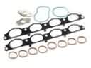 Chevrolet Tracker Intake Manifold Gasket
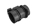 Chevrolet Tracker Mass Air Flow Sensor
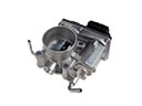 Chevrolet Tracker Throttle Body
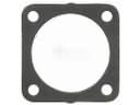 Chevrolet Tracker Throttle Body Gasket
 Chevrolet Tracker Vapor Pressure Sensor