ChevyParts
My Garage
My Account
Cart
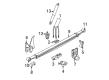
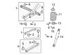
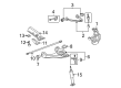
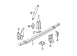
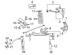
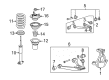
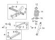
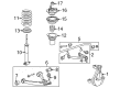
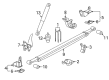
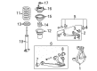
OEM Chevrolet Suburban 2500 Shock Absorber
Suspension Shock Absorber- Select Vehicle by Model
- Select Vehicle by VIN
Select Vehicle by Model
orMake
Model
Year
Select Vehicle by VIN
For the most accurate results, select vehicle by your VIN (Vehicle Identification Number).
33 Shock Absorbers found


Chevrolet Suburban 2500 Shock Absorber Part Number: 89038654
$75.72 MSRP: $146.97You Save: $71.25 (49%)Ships in 1-2 Business Days


Chevrolet Suburban 2500 Shock Absorber, Black, Rear Part Number: 19368462
$358.90 MSRP: $696.56You Save: $337.66 (49%)Ships in 1-3 Business Days


Chevrolet Suburban 2500 Shock Absorber Part Number: 20951274
$36.05 MSRP: $109.39You Save: $73.34 (68%)Ships in 1-2 Business Days

Chevrolet Suburban 2500 Shock Absorber Part Number: 25984611
$67.49 MSRP: $134.25You Save: $66.76 (50%)Ships in 1 Business Day

Chevrolet Suburban 2500 Shock Absorber Part Number: 25980102
$140.80 MSRP: $254.83You Save: $114.03 (45%)Ships in 1-2 Business Days
Chevrolet Suburban 2500 Shock Absorber Part Number: 20951275
$85.20 MSRP: $160.01You Save: $74.81 (47%)Ships in 1-2 Business Days

Chevrolet Suburban 2500 Shock, Rear Part Number: 12477645
$416.32 MSRP: $828.19You Save: $411.87 (50%)Ships in 1-2 Business Days

Chevrolet Suburban 2500 Shock Absorber Part Number: 25871227
$135.78 MSRP: $245.75You Save: $109.97 (45%)Ships in 1 Business Day
Chevrolet Suburban 2500 Shock Absorber Part Number: 25871231
$96.00 MSRP: $173.80You Save: $77.80 (45%)Ships in 1-2 Business Days
Chevrolet Suburban 2500 Shock Absorber Part Number: 22755311
$89.67 MSRP: $162.28You Save: $72.61 (45%)Ships in 1-2 Business Days

Chevrolet Suburban 2500 Shock Absorber Part Number: 20955500
$93.05 MSRP: $198.62You Save: $105.57 (54%)Ships in 1-2 Business Days

Chevrolet Suburban 2500 Shock Absorber Part Number: 20955497
$65.72 MSRP: $185.10You Save: $119.38 (65%)Ships in 1-2 Business Days


Chevrolet Suburban 2500 Shock Absorber, Front Part Number: 19209331
$76.18 MSRP: $151.52You Save: $75.34 (50%)Ships in 1-2 Business Days
Chevrolet Suburban 2500 Shock Absorber Part Number: 20765198
$108.18 MSRP: $195.80You Save: $87.62 (45%)Ships in 1-2 Business Days
Chevrolet Suburban 2500 Shock Absorber Part Number: 20955408
$48.56 MSRP: $136.83You Save: $88.27 (65%)Ships in 1-2 Business Days
Chevrolet Suburban 2500 Shock Absorber, Front Part Number: 19420489
$333.45 MSRP: $647.16You Save: $313.71 (49%)Ships in 1-2 Business Days
Chevrolet Suburban 2500 Shock Absorber Part Number: 20906291
$84.74 MSRP: $159.16You Save: $74.42 (47%)Ships in 1-2 Business DaysChevrolet Suburban 2500 Shock Absorber Part Number: 20951277
$53.62 MSRP: $106.65You Save: $53.03 (50%)Ships in 1-2 Business Days
Chevrolet Suburban 2500 Shock Absorber Part Number: 20958798
$112.08 MSRP: $201.03You Save: $88.95 (45%)Ships in 1-2 Business Days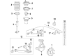
Chevrolet Suburban 2500 Shock Absorber Part Number: 20765177
$152.87 MSRP: $274.19You Save: $121.32 (45%)
| Page 1 of 2 |Next >
1-20 of 33 Results
Chevrolet Suburban 2500 Shock Absorber
Want to cut long-term maintenance and repair costs? Choose OEM Shock Absorber. Those parts deliver top durability you can trust. On our site, you'll find a huge catalog of genuine Chevrolet Suburban 2500 parts. Prices are unbeatable, so you can keep more in your pocket. Every OEM Chevrolet Suburban 2500 Shock Absorber includes a manufacturer's warranty. You can also get an easy return policy that keeps buying risk free. Fast delivery, get your car on the road quickly. It's simple to search, compare, and order. Stop guessing about quality or fit. Order today and save with parts that last.
Chevrolet Suburban 2500 Shock Absorber Parts and Q&A
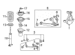
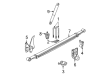
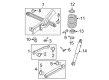
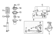
- Q: How to replace a shock absorber on Chevrolet Suburban 2500?A:The vehicle needs to be raised through a lift then supported before starting the Shock Absorber replacement process by installing jack stands below the lower Control Arm. The technician should first disconnect the (RTD) link rod from the sensor device and remove the electrical connector if the vehicle has selectable ride. Rephrase the following sentence. Also normalize verbalization when possible. The connector lock tabs (1, 2) should be rotated counterclockwise to unlock the connector, which can be disengaged by pulling upwards. Have a wrench ready to hold the tennon end while removing the nut before taking out the upper insulator except for the plastic pilot ring. Disassemble the Shock Absorber mounting bolt at the lower Control Arm for 15 series and 25/35 series vehicles and the Shock Absorber can be extracted. Before mounting the Shock Absorber stem must pass through the shock bracket opening on the frame until it lines up with both lower Control Arm holes from both series. Mount the Shock Absorber by passing it through the lower Control Arm bolt which leads to the bolt nut then complete tightening this nut to 80 nm (59 ft. Lbs.). The upper insulator needs to go on top of the shock mounting bracket on the frame with the plastic pilot ring used to align it properly. The Shock Absorber receives the upper insulator followed by attaching the nut to the tennon end without tightening it. Connect the rtd link rod to the sensor if it exists and then take away safety stands before lowering the vehicle. A wrench should be applied to the tennon end while tightening the nut to 20 nm (15 ft. Lbs.). Verify selectable ride equipment has an unlocked connector before aligning the tabs perpendicular to the wrench flats on the tennon end and engaging by firm downward pressure. Rotate the lock tabs (1, 2) counterclockwise until they snap into place along with an audible noise while maintaining their perpendicular alignment with the wrench flats on the tennon end. Finally, dispose of the Shock Absorber.

Related Chevrolet Suburban 2500 Parts
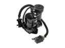 Chevrolet Suburban 2500 Air Suspension Compressor
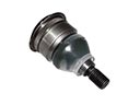 Chevrolet Suburban 2500 Ball Joint
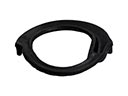 Chevrolet Suburban 2500 Coil Spring Insulator
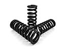 Chevrolet Suburban 2500 Coil Springs
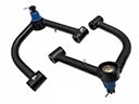 Chevrolet Suburban 2500 Control Arm
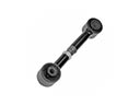 Chevrolet Suburban 2500 Lateral Link
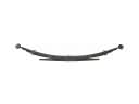 Chevrolet Suburban 2500 Leaf Spring
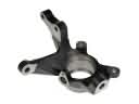 Chevrolet Suburban 2500 Steering Knuckle
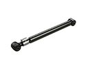 Chevrolet Suburban 2500 Suspension Strut Rod
 Chevrolet Suburban 2500 Sway Bar Bracket
 Chevrolet Suburban 2500 Sway Bar Bushing
 Chevrolet Suburban 2500 Trailing Arm