ChevyParts
My Garage
My Account
Cart
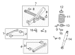
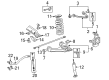
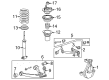
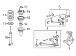
OEM Chevrolet Suburban 1500 Control Arm
Suspension Arm- Select Vehicle by Model
- Select Vehicle by VIN
Select Vehicle by Model
orMake
Model
Year
Select Vehicle by VIN
For the most accurate results, select vehicle by your VIN (Vehicle Identification Number).
18 Control Arms found


Chevrolet Suburban 1500 Upper Control Arm, Rear Part Number: 20917465
$48.96 MSRP: $97.41You Save: $48.45 (50%)Ships in 1-2 Business Days


Chevrolet Suburban 1500 Lower Control Arm, Rear Part Number: 22868629
$52.53 MSRP: $91.66You Save: $39.13 (43%)Ships in 1-2 Business Days


Chevrolet Suburban 1500 Upper Control Arm Part Number: 25905442
$166.52 MSRP: $290.58You Save: $124.06 (43%)Ships in 1-2 Business Days


Chevrolet Suburban 1500 Lower Control Arm, Passenger Side Part Number: 20869202
$317.05 MSRP: $553.26You Save: $236.21 (43%)
Chevrolet Suburban 1500 Lower Control Arm, Driver Side Part Number: 20869201
$317.05 MSRP: $553.26You Save: $236.21 (43%)


Chevrolet Suburban 1500 Upper Control Arm, Passenger Side Part Number: 25812726
$173.34 MSRP: $298.01You Save: $124.67 (42%)Ships in 1-2 Business Days


Chevrolet Suburban 1500 Upper Control Arm, Driver Side Part Number: 25812725
$173.34 MSRP: $298.01You Save: $124.67 (42%)Ships in 1-2 Business Days


Chevrolet Suburban 1500 Lower Control Arm, Passenger Side Part Number: 25997510
$372.58 MSRP: $639.89You Save: $267.31 (42%)Ships in 1-3 Business Days

Chevrolet Suburban 1500 Upper Control Arm, Rear Part Number: 15767252
$96.24 MSRP: $158.55You Save: $62.31 (40%)Ships in 1-3 Business Days
Chevrolet Suburban 1500 Lower Control Arm, Driver Side Part Number: 25997509
$388.44 MSRP: $639.89You Save: $251.45 (40%)


Chevrolet Suburban 1500 Lower Control Arm, Driver Side Part Number: 20832022
$597.53 MSRP: $849.05You Save: $251.52 (30%)Ships in 1-3 Business DaysChevrolet Suburban 1500 Lower Control Arm, Driver Side Part Number: 12478067
$124.29 MSRP: $204.73You Save: $80.44 (40%)

Chevrolet Suburban 1500 Upper Control Arm Part Number: 12475485
$97.16 MSRP: $152.05You Save: $54.89 (37%)

Chevrolet Suburban 1500 Lower Control Arm, Passenger Side Part Number: 12475480
$280.32 MSRP: $445.05You Save: $164.73 (38%)Ships in 1-3 Business Days
Chevrolet Suburban 1500 Lower Control Arm, Driver Side Part Number: 12475479
$292.45 MSRP: $460.16You Save: $167.71 (37%)

Chevrolet Suburban 1500 Upper Control Arm, Front Part Number: 15864153


Chevrolet Suburban 1500 Control Arm
Want to cut long-term maintenance and repair costs? Choose OEM Control Arm. Those parts deliver top durability you can trust. On our site, you'll find a huge catalog of genuine Chevrolet Suburban 1500 parts. Prices are unbeatable, so you can keep more in your pocket. Every OEM Chevrolet Suburban 1500 Control Arm includes a manufacturer's warranty. You can also get an easy return policy that keeps buying risk free. Fast delivery, get your car on the road quickly. It's simple to search, compare, and order. Stop guessing about quality or fit. Order today and save with parts that last.
Chevrolet Suburban 1500 Control Arm Parts and Q&A
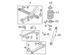
- Q: How to replace the rear axle lower control arm on Chevrolet Suburban 1500?A:The replacement process for the rear axle lower control arm requires support for the vehicle when elevated. You need to first remove the lower control arm retaining nuts and the retaining bolt before extracting the lower control arm. The first step for installation involves putting in the lower control arm followed by the retaining bolts and their installation procedure must wait until reaching ride height according to Fastener Notice in Cautions and Notices. Put in the lower control arm retaining nut next followed by tightening the retaining bolts to 120 Nm (89 ft. lbs.). To complete the procedure first remove the rear axle support and lower the vehicle.
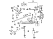
- Q: How to service and repair the front upper control arm on Chevrolet Suburban 1500?A:Start the front upper Control Arm service and repair process only after you raise and stabilize the vehicle. Before starting work on the front upper Control Arm remove the tire and wheel and disconnect the real time damping (RTD) link rod from the sensor if present. Starting with the brake hose and wheel speed sensor bracket retaining bolts the service moves to the wheel drive shaft. For the upper Ball Joint repair start by removing its nut which then gets discarded. The j 43631 (Ball Joint Separator) allows disconnection of the upper Control Arm from the Steering Knuckle. Both the upper Control Arm nuts and adjustment cams must be removed from all models of the 15 series rwd, 15 series 4wd, and 25 series rwd while the upper Control Arm bolts need to be removed from each series. The installation order for the 25 series 4wd includes upper Control Arm bolts followed by upper Control Arm nuts and adjustment cams for the same series. Tighten both components to 190 nm (140 ft. Lbs.). The same procedure applies successively to 15 series rwd together with 4wd and 25 series rwd. Connect the upper Control Arm to the Steering Knuckle after reinstalling the wheel drive shaft and install a new nut on the upper Ball Joint stud. Tighten the nut to 100 nm (74 ft. Lbs.). Reinstall brake hose motor and wheel speed sensor retainers using 9 nm (80 inch lbs.) torque settings followed by connecting the rtd link rod to the sensor if the vehicle includes the system. After wheel reinstallation you must remove safety stands until the vehicle reaches the floor then perform a wheel alignment check.


Related Chevrolet Suburban 1500 Parts
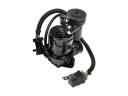 Chevrolet Suburban 1500 Air Suspension Compressor
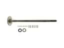 Chevrolet Suburban 1500 Axle Shaft
 Chevrolet Suburban 1500 Ball Joint
 Chevrolet Suburban 1500 Coil Springs
 Chevrolet Suburban 1500 Control Arm Bushing
 Chevrolet Suburban 1500 Lateral Link
 Chevrolet Suburban 1500 Leaf Spring Plate
 Chevrolet Suburban 1500 Leaf Spring Shackle
 Chevrolet Suburban 1500 Sway Bar Bushing
 Chevrolet Suburban 1500 Sway Bar Link Bushing
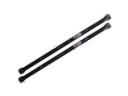 Chevrolet Suburban 1500 Torsion Bar
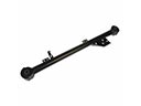 Chevrolet Suburban 1500 Trailing Arm