ChevyParts
My Garage
My Account
Cart
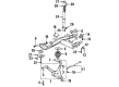
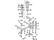
OEM 2004 Buick LeSabre Control Arm
Suspension Arm- Select Vehicle by Model
- Select Vehicle by VIN
Select Vehicle by Model
orMake
Model
Year
Select Vehicle by VIN
For the most accurate results, select vehicle by your VIN (Vehicle Identification Number).
4 Control Arms found


 Product Specifications
- Other Name: Arm Assembly-Rear Suspension Control; Lower Control Arm; Arm, Rear Axle Control Arm
- Position: Passenger Side
- Replaces: 15897790, 25771881
- Item Weight: 17.60 Pounds
- Item Dimensions: 27.8 x 20.7 x 8.0 inches
- Condition: New
- Fitment Type: Direct Replacement
- SKU: 25820033
- Warranty: This genuine part is guaranteed by GM's factory warranty.


2004 Buick LeSabre Control Arm, Rear Driver Side Part Number: 25820031
Product Specifications- Other Name: Arm Assembly-Rear Suspension Control; Lower Control Arm; Arm, Rear Axle Control Arm
- Position: Driver Side
- Replaces: 15897788, 25690655, 25765590, 25743300, 25628897, 25626733, 25675172, 25699091
- Item Weight: 16.50 Pounds
- Item Dimensions: 30.6 x 22.3 x 8.3 inches
- Condition: New
- Fitment Type: Direct Replacement
- SKU: 25820031
- Warranty: This genuine part is guaranteed by GM's factory warranty.


2004 Buick LeSabre Control Arm, Driver Side Part Number: 25766511
Product Specifications- Other Name: Arm, Steering Knuckle Upper & Lower Control; Suspension Control Arm and Ball Joint Assembly; Control Arm Assembly
- Position: Driver Side
- Replaces: 25702221, 25696334, 25672870, 25746324, 25699467, 25766508, 25745395, 88967801, 88986632, 25703055
- Item Weight: 8.50 Pounds
- Item Dimensions: 18.8 x 16.2 x 4.4 inches
- Condition: New
- Fitment Type: Direct Replacement
- SKU: 25766511
- Warranty: This genuine part is guaranteed by GM's factory warranty.

2004 Buick LeSabre Control Arm, Passenger Side Part Number: 25766510
Product Specifications- Other Name: Arm, Steering Knuckle Upper & Lower Control; Suspension Control Arm and Ball Joint Assembly; Control Arm Assembly
- Position: Passenger Side
- Replaces: 19202594, 25699468, 25746325, 25702222, 25766509, 25672871, 25696335, 88986633, 25703056
- Item Weight: 8.40 Pounds
- Item Dimensions: 18.8 x 16.4 x 4.3 inches
- Condition: New
- Fitment Type: Direct Replacement
- SKU: 25766510
- Warranty: This genuine part is guaranteed by GM's factory warranty.
2004 Buick LeSabre Control Arm
With a comprehensive array of OEM 2004 Buick LeSabre Control Arm, from fuel pumps to door handles, our website is a one-stop-shop for your needs. All our genuine 2004 Buick LeSabre Control Arm are backed by the manufacturer's warranty and are offered at competitive prices in the market. Rest assured, you can shop with complete confidence.
2004 Buick LeSabre Control Arm Parts and Q&A
- Q: How to replace the lower control arm in the front suspension on 2004 Buick LeSabre?A: To replace the lower Control Arm of the front suspension, lift and support the vehicle, the tire and wheel and the lastly the stabilizer shaft link. Then, take out the cotter pin and loosen the lower Ball Joint retaining nut from the ball stud, and make sure that the over-extension of the tri-pot joints is avoided, as its internal component separation and failure. Utilise the j43828 Ball Joint separator (J43828) to remove the lower Ball Joint from the Steering Knuckle, after this remove the lower Ball Joint retaining nut and finally the lower control-arm-mounting bolts and nuts that will hold the lower control-arm to the frame. In installation, hook the lower Control Arm to the frame without tightening the Control Arm nuts first. Support vehicle weight with the use of the control arms in order to establish correct trim height prior to installation of the lower bolts, Control Arm and nuts. Mount and tighten the lower Ball Joint and retaining nut to the Steering Knuckle ensuring that it is tightened to 10 nm (89 inch lbs.) and another 180 degrees with at no point being more than two slots away from a cotter pin alignment. Once the cotter pin is in place, install it, reconnect the stabilizer shaft link, tire, and wheel, lower the vehicle, and check the trim height. Finally, adjust the Control Arm bolts in sequence with rear mounting bolt 158 nm 117ft.lbs., and not mounting nut 158 nm 117ft.lbs.
Related 2004 Buick LeSabre Parts
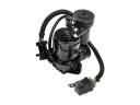 2004 Buick LeSabre Air Suspension Compressor
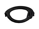 2004 Buick LeSabre Coil Spring Insulator
 2004 Buick LeSabre Coil Springs
 2004 Buick LeSabre Ride Height Sensor
 2004 Buick LeSabre Shock Absorber
 2004 Buick LeSabre Shock And Strut Mount
 2004 Buick LeSabre Spindle Nut
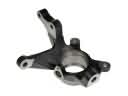 2004 Buick LeSabre Steering Knuckle
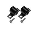 2004 Buick LeSabre Sway Bar Bushing
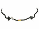 2004 Buick LeSabre Sway Bar Kit
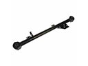 2004 Buick LeSabre Trailing Arm
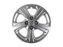 2004 Buick LeSabre Wheel Cover