ChevyParts
My Garage
My Account
Cart
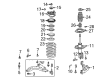
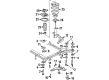
OEM 2000 Cadillac DeVille Steering Knuckle
Front Steering Knuckle- Select Vehicle by Model
- Select Vehicle by VIN
Select Vehicle by Model
orMake
Model
Year
Select Vehicle by VIN
For the most accurate results, select vehicle by your VIN (Vehicle Identification Number).
3 Steering Knuckles found


2000 Cadillac DeVille Knuckle, Driver Side Part Number: 23127629
$268.88 MSRP: $442.93You Save: $174.05 (40%)Ships in 1-2 Business DaysProduct Specifications- Other Name: Knuckle, Steering (Machining); Knuckle, Steering
- Position: Driver Side
- Replaces: 10434254, 18060680, 18060652, 18060638, 20899802, 25816684, 88955418, 22990752
- Item Weight: 5.30 Pounds
- Item Dimensions: 5.8 x 12.9 x 12.5 inches
- Condition: New
- Fitment Type: Direct Replacement
- SKU: 23127629
- Warranty: This genuine part is guaranteed by GM's factory warranty.

2000 Cadillac DeVille Knuckle, Passenger Side Part Number: 18060635
$205.54 MSRP: $376.96You Save: $171.42 (46%)Ships in 1-2 Business DaysProduct Specifications- Other Name: Knuckle, Steering
- Position: Passenger Side
- Replaces: 18021762, 18026646
- Item Weight: 5.80 Pounds
- Item Dimensions: 11.7 x 11.1 x 5.5 inches
- Condition: New
- Fitment Type: Direct Replacement
- SKU: 18060635
- Warranty: This genuine part is guaranteed by GM's factory warranty.


2000 Cadillac DeVille Knuckle, Driver Side Part Number: 18060634
Product Specifications- Other Name: Knuckle, Steering
- Position: Driver Side
- Replaces: 18021761
- Item Weight: 6.60 Pounds
- Item Dimensions: 11.4 x 11.3 x 7.3 inches
- Condition: New
- Fitment Type: Direct Replacement
- SKU: 18060634
- Warranty: This genuine part is guaranteed by GM's factory warranty.
2000 Cadillac DeVille Steering Knuckle
With a comprehensive array of OEM 2000 Cadillac DeVille Steering Knuckle, from fuel pumps to door handles, our website is a one-stop-shop for your needs. All our genuine 2000 Cadillac DeVille Steering Knuckle are backed by the manufacturer's warranty and are offered at competitive prices in the market. Rest assured, you can shop with complete confidence.
2000 Cadillac DeVille Steering Knuckle Parts and Q&A
- Q: How to service and repair the steering knuckle for RPO FE1 and FE3 on 2000 Cadillac DeVille?A: To service and repair the Steering Knuckle in the case of rpo fe1 and fe3, start by lifting the vehicle and removing wheel and tire. Secondly, extract the wheel drive shaft nut, then the lower Ball Joint cotter pin and nut. Loosen the brake caliper bolts and prop up the caliper from the brake rotor before you remove the rotor. Unplug the wheel speed sensor and remove the retaining bolts for the wheel and bearing. Unscrew the hex socket screw (H15203), using the wobble screw tip torque head bag & handle screwdriver (J2110-A), then remove the hex nut (T34009). Use the hub and bearing puller (J28733-B) to remove the hub and drive axle. Finally, with the help of the steering linkage and Tie Rod puller (J24319-B), separate the Tie Rod from Steering Knuckle. Use the Ball Joint separator (J43828) to remove the Ball Joint from the Steering Knuckle firstly and then remove the strut to knuckle attaching nuts and bolts to extract the Steering Knuckle. During installation, fasten the Steering Knuckle onto the strut, tightening it to 147 nm (108 ft. Lbs.) of the strut to knuckle. Connect lower Ball Joint, install lower page joint nut which should be tightened to 10 nm (88 inch lbs) and then turn an additional of 150 degrees, with cotter pin to align properly, without backing off nut. Install a new cotter pin, then the Tie Rod attaching the same to the knuckle nut tightening to 30 nm (22 ft. Lbs.) plus extra of 200, again making sure of matching the cotter pin. Mount the hub and bearing to Steering Knuckle/drive axle, then the hub and the bearing retaining bolts in a cross pattern, drawing the bolts to a high torque of 130 nm (96 ft. Lbs.). Put the caliper back and rotor and reconnect the wheel speed sensor connector. Apply a pry bar between the brake caliper and the rotor to prevent the wheel driveshaft from spinning during the installation of the drive axle nut, tightening it to 160 nm (118 ft. Lbs.). Finally, install the wheel and tires, tightened to 125 nm (80 ft. Lbs), and check the alignment of the wheels.
Related 2000 Cadillac DeVille Parts
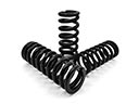 2000 Cadillac DeVille Coil Springs
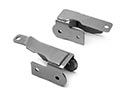 2000 Cadillac DeVille Control Arm Bracket
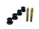 2000 Cadillac DeVille Crossmember Bushing
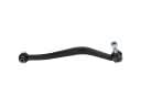 2000 Cadillac DeVille Lateral Arm
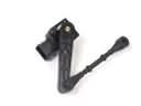 2000 Cadillac DeVille Ride Height Sensor
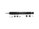 2000 Cadillac DeVille Shock Absorber
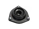 2000 Cadillac DeVille Shock And Strut Mount
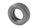 2000 Cadillac DeVille Strut Bearing
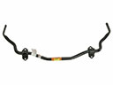 2000 Cadillac DeVille Sway Bar Kit
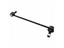 2000 Cadillac DeVille Sway Bar Link
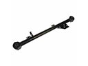 2000 Cadillac DeVille Trailing Arm
 2000 Cadillac DeVille Wheel Bearing