ChevyParts
My Garage
My Account
Cart
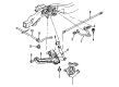
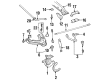
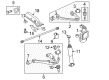
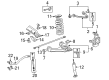
OEM GMC Sierra 1500 Torsion Bar
Suspension Torsion Bar- Select Vehicle by Model
- Select Vehicle by VIN
Select Vehicle by Model
orMake
Model
Year
Select Vehicle by VIN
For the most accurate results, select vehicle by your VIN (Vehicle Identification Number).
10 Torsion Bars found


GMC Sierra 1500 Torsion Bar, Front Part Number: 15048312
$257.64 MSRP: $405.40You Save: $147.76 (37%)Ships in 1-3 Business Days

GMC Sierra 1500 Torsion Bar, Front Driver Side Part Number: 19330060
$320.53 MSRP: $504.33You Save: $183.80 (37%)
GMC Sierra 1500 Torsion Bar, Front Passenger Side Part Number: 19330059
$320.53 MSRP: $504.33You Save: $183.80 (37%)Ships in 1-3 Business Days


GMC Sierra 1500 Torsion Bar, Front Driver Side Part Number: 19330058
$320.58 MSRP: $504.42You Save: $183.84 (37%)

GMC Sierra 1500 Torsion Bar, Front Passenger Side Part Number: 19330057
$320.58 MSRP: $504.42You Save: $183.84 (37%)


GMC Sierra 1500 Torsion Bar, Front Passenger Side Part Number: 19332946
$257.82 MSRP: $405.67You Save: $147.85 (37%)
GMC Sierra 1500 Torsion Bar, Front Driver Side Part Number: 19332945
$257.82 MSRP: $405.67You Save: $147.85 (37%)
GMC Sierra 1500 Torsion Bar, Front Driver Side Part Number: 19330062
GMC Sierra 1500 Torsion Bar, Front Part Number: 19332931
GMC Sierra 1500 Torsion Bar
Want to cut long-term maintenance and repair costs? Choose OEM Torsion Bar. Those parts deliver top durability you can trust. On our site, you'll find a huge catalog of genuine GMC Sierra 1500 parts. Prices are unbeatable, so you can keep more in your pocket. Every OEM GMC Sierra 1500 Torsion Bar includes a manufacturer's warranty. You can also get an easy return policy that keeps buying risk free. Fast delivery, get your car on the road quickly. It's simple to search, compare, and order. Stop guessing about quality or fit. Order today and save with parts that last.
GMC Sierra 1500 Torsion Bar Parts and Q&A
- Q: How to replace the torsion bar and support assembly (bushing style) on GMC Sierra 1500?A:The first step to replace bushing-style Torsion Bar and support assembly requires raising and supporting the vehicle. Place the Torsion Bar unloading/loading tool j 36202 onto the crossmember and adjustment arm before beginning the procedure. Apply tension to the adjustment arm with the j 36202 until the adjuster nut and adjustment bolt become unloaded after marking the bolt position. Record the required turns needed for bolt removal. The adjustment bolt and the adjuster nut from the crossmember must be removed before taking out the j 36202 so the Torsion Bar can unload. Remove the adjustment arm and Torsion Bar crossmember bolt from its weld nut before pulling the crossmember out from its mount. Remove the Torsion Bar from the crossmember while keeping in mind that left and right bars differ by design and do not fit one another before extracting all torsion bars from the vehicle. Install the Torsion Bar into its position in the lower Control Arm before placing it on the crossmember mount. Screw the Torsion Bar crossmember bolt into the weld nut before tightening it to 95 n.m (70 lb ft). First position the adjustment arm inside the crossmember before inserting the adjuster bolt and adjuster nut. Insert the Torsion Bar completely into the adjustment arm before reinstalling the j 36202 to both the adjustment arm and crossmember. Apply torque force to the adjustment arm while using j 36202 until the Torsion Bar reaches maximum load. Use the same number of turns on the adjuster bolt as when it was removed. Use the j 36202 to measure the z height after removing it from the crossmember. Next, remove the safety stands and lower the vehicle before taking z height measurements.

Related GMC Sierra 1500 Parts
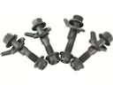 GMC Sierra 1500 Camber and Alignment Kit
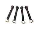 GMC Sierra 1500 Control Arm Bolt
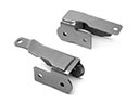 GMC Sierra 1500 Control Arm Bracket
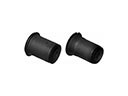 GMC Sierra 1500 Control Arm Bushing
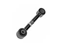 GMC Sierra 1500 Lateral Link
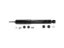 GMC Sierra 1500 Shock Absorber
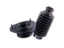 GMC Sierra 1500 Shock and Strut Boot
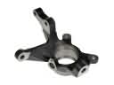 GMC Sierra 1500 Steering Knuckle
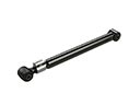 GMC Sierra 1500 Suspension Strut Rod
 GMC Sierra 1500 Sway Bars
 GMC Sierra 1500 Track Bar
 GMC Sierra 1500 Trailing Arm