ChevyParts
My Garage
My Account
Cart
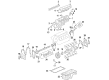
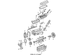
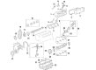
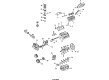
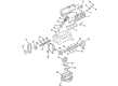
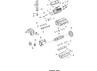
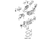
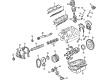
OEM Chevrolet Monte Carlo Rocker Arm
Engine Rocker Arm- Select Vehicle by Model
- Select Vehicle by VIN
Select Vehicle by Model
orMake
Model
Year
Select Vehicle by VIN
For the most accurate results, select vehicle by your VIN (Vehicle Identification Number).
10 Rocker Arms found


Chevrolet Monte Carlo Rocker Arms Part Number: 10214664
$14.80 MSRP: $24.39You Save: $9.59 (40%)Ships in 1-2 Business Days

Chevrolet Monte Carlo Rocker Arms Part Number: 10089648
$27.26 MSRP: $44.94You Save: $17.68 (40%)Ships in 1-2 Business Days
Chevrolet Monte Carlo Rocker Arms Part Number: 12577695
$26.17 MSRP: $41.53You Save: $15.36 (37%)Ships in 1-3 Business Days
Chevrolet Monte Carlo Rocker Arms Part Number: 1241851
$13.11


Chevrolet Monte Carlo Rocker Arms Part Number: 24504436

Chevrolet Monte Carlo Rocker Arms Part Number: 12576628
$19.02 MSRP: $29.79You Save: $10.77 (37%)
Chevrolet Monte Carlo Rocker Arms, Passenger Side Part Number: 1241850

Chevrolet Monte Carlo Rocker Arms Part Number: 22505583
Chevrolet Monte Carlo Rocker Arms Part Number: 12521876

Chevrolet Monte Carlo Rocker Arms Part Number: 24503999
Chevrolet Monte Carlo Rocker Arm
Want to cut long-term maintenance and repair costs? Choose OEM Rocker Arm. Those parts deliver top durability you can trust. On our site, you'll find a huge catalog of genuine Chevrolet Monte Carlo parts. Prices are unbeatable, so you can keep more in your pocket. Every OEM Chevrolet Monte Carlo Rocker Arm includes a manufacturer's warranty. You can also get an easy return policy that keeps buying risk free. Fast delivery, get your car on the road quickly. It's simple to search, compare, and order. Stop guessing about quality or fit. Order today and save with parts that last.
One of the significant parts in the Chevrolet Monte Carlo vehicles is the Rocker Arm, which plays an essential role in valvetrain system, where the motion of pushrod is provided to the valves such as the intake and exhaust. Traditionally made of stamped steel or aluminum, these rocker arms transfer lateral pushrod oscillation into the desired up and down movement to open the valves. For highly rpm applications aluminum is used since it is light whereas for durability cast iron or forged carbon steel is used in diesel engines. Rocker arms on Chevrolet Monte Carlo may vary in type such as the traditional rocker arms and roller rocker arms. Roller rockers, which incorporate needle bearings decrease friction and thus wear making the performance of these rockers better as opposed to others. The rocker ratio, that is between 1.5:1 and 1.8:1 in modern engines, enables the camshaft to produce higher lift and hence better performance of the engine. Better fulcrum bearings are also used in Chevrolet Monte Carlo car engines with high RPM levels to cater for the stress and prolong the durability.
Chevrolet Monte Carlo Rocker Arm Parts and Q&A
- Q: How to service and repair the rocker arm assembly on Chevrolet Monte Carlo?A:The valve rocker arm cover(s) need to be removed first before starting rocker arm assembly repair and maintenance. Begin valve rocker arm service by removing the bolt(s) using the required steps and setting all components on a clean surface before storage for reinstallation sequence. Continue the procedure by removing the valve rocker arm(s) along with the complete valve rocker arm guide plate when all rocker arms are being replaced before installing the push rod(s). The push rod(s) and valve rocker arm(s) as well as bolt(s) and guide plate(s) need cleaning in a suitable solution while cleaning all thread adhesive from the valve rocker arm bolt(s). To install the cylinder head probes you must use the J 36660-A Torque Angle Meter to remove oil from the tapped holes by blowing compressed air through them. Fit new engine oil on the push rod ends before mounting them back to their original positions. The mechanic needs to install both the valve rocker arm guide plates and each of the valve rocker arms. The correct part number fastener is essential for the rocker arm pedestal retaining bolt(s) to prevent damage therefore apply GM P/N 12345493 threadlock or equivalent to the bolt threads. Secure the rocker arm bolts to 15 Nm (11 ft. lbs.) while applying the J 36660-A tool to turn the bolts by 90 degrees. After valve rocker arm cover installation place the valve train under noise inspection.
- Q: How to replace the valve rocker arm and push rod on Chevrolet Monte Carlo?A:The first step for replacing the valve Rocker Arm and push rod is to remove the valve Rocker Arm cover. The rack will hold valve Rocker Arm and Pushrod and pivot support in their original positions. Follow this step by the valve Rocker Arm bolt and then remove the valve Rocker Arm and pivot support and Pushrod. The cleaning and examination process of valve Rocker Arm and Pushrod must be completed. The valve train components need to be reinstalled at their factory locations without any adjustment of valve lash since the net build design requires no alteration. Clean engine oil should be used to lubricate both the valve Rocker Arm and Pushrod as well as the valve Rocker Arm bolt flange. Set the Pushrod in its appropriate position in the valve lifter socket of the valve Rocker Arm pivot support before installing the Pushrod. The Pushrod must correctly sit at the Rocker Arm ends before adjusting the Rocker Arm bolt torque. Fasten the Rocker Arm in place before rotating the Crankshaft until piston number one reaches top dead center compression position with the key of the Crankshaft sprocket at 1:30. The engine layout features the left bank containing cylinders 1, 3, 5 and 7 while the right bank contains cylinders 2, 4, 6 and 8 during this specific position. Keep the Crankshaft at engine firing position number one to tighten exhaust valve rocker bolts of cylinders 1, 2, 7 and 8 up to 30 nm (22 ft. Lbs.) while intake valve rocker bolts of cylinders 1, 3, 4 and 5 require the same 30 nm (22 ft. Lbs.) torque setting. Perform Crankshaft rotation 360 degrees and proceed to tighten valve Rocker Arm bolts for cylinders 3, 4, 5, 6 exhaust to 30 nm (22 ft. Lbs.) and for cylinders 2, 6, 7, 8 intake to 30 nm (22 ft. Lbs.). The valve Rocker Arm cover should be the last step in the installation process.


Related Chevrolet Monte Carlo Parts
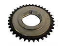 Chevrolet Monte Carlo Balance Shaft Gear
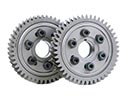 Chevrolet Monte Carlo Cam Gear
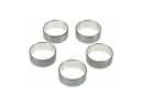 Chevrolet Monte Carlo Camshaft Bearing
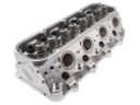 Chevrolet Monte Carlo Cylinder Head
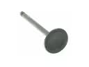 Chevrolet Monte Carlo Intake Valve
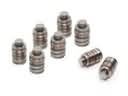 Chevrolet Monte Carlo Lash Adjuster
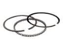 Chevrolet Monte Carlo Piston Ring Set
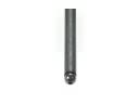 Chevrolet Monte Carlo Pushrod
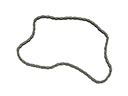 Chevrolet Monte Carlo Timing Chain
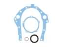 Chevrolet Monte Carlo Timing Cover Gasket
 Chevrolet Monte Carlo Valve Cover Grommet
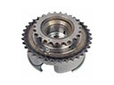 Chevrolet Monte Carlo Variable Timing Sprocket