ChevyParts
My Garage
My Account
Cart
OEM Chevrolet Metro Steering Knuckle
Front Steering Knuckle- Select Vehicle by Model
- Select Vehicle by VIN
Select Vehicle by Model
orMake
Model
Year
Select Vehicle by VIN
For the most accurate results, select vehicle by your VIN (Vehicle Identification Number).
7 Steering Knuckles found

Chevrolet Metro Knuckle, Rear Driver Side Part Number: 30013299
Chevrolet Metro Knuckle, Rear Passenger Side Part Number: 30013298
Chevrolet Metro Knuckle, Rear Passenger Side Part Number: 30013297

Chevrolet Metro Knuckle, Driver Side Part Number: 30013293
Chevrolet Metro Knuckle, Driver Side Part Number: 30013292

Chevrolet Metro Knuckle, Passenger Side Part Number: 30013291
Chevrolet Metro Knuckle, Passenger Side Part Number: 30013290
Chevrolet Metro Steering Knuckle
Want to cut long-term maintenance and repair costs? Choose OEM Steering Knuckle. Those parts deliver top durability you can trust. On our site, you'll find a huge catalog of genuine Chevrolet Metro parts. Prices are unbeatable, so you can keep more in your pocket. Every OEM Chevrolet Metro Steering Knuckle includes a manufacturer's warranty. You can also get an easy return policy that keeps buying risk free. Fast delivery, get your car on the road quickly. It's simple to search, compare, and order. Stop guessing about quality or fit. Order today and save with parts that last.
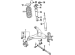
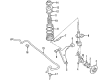
The Steering Steering Steering Knuckle in Chevrolet Metro is designed to connect the suspension order and the steering order in order to enable the movement of the front wheels. It has provision for control arms, tie-rod ends and the spindle or hub, allowing the up and down wheel movement as per road surface irregularities and out to in movement during steering. Chevrolet Metro steering knuckles can be sorted with respect to drive layouts- front wheel drive (FWD) and rear wheel drive (RWD). Fwd/awd/4wd models have an extended drive axle through the knuckle and terminating in a hub, while rwd cars might have an integral spindle or bolted-in hub. In terms of performance and durability the steering knuckle has advanced from the kingpin type to the current ball joint type. There must always be inspection more often as it is proven that some of these components may degrade especially after suspension work.
Chevrolet Metro Steering Knuckle Parts and Q&A
- Q: How to service and repair the steering knuckle on Chevrolet Metro?A:In servicing and repairing the Steering Knuckle, one should start by lifting and supporting the vehicle. Take off the tire and wheel assembly, then the brake caliper, caliper carrier, and rotor. For abs equipped vehicles, unplug the Wheel Speed Sensor electrical connector and remove Wheel Speed Sensor from the knuckle with one bolt. Unstake and remove drive axle nut and washer. If you are going to replace the knuckle, remove the hub with two wheel nuts, the wheel hub remover (J 34866), and the slide hammer (J2619-01). Take away the cotter pin and castle nut from the Tie Rod End before removing the Tie Rod End from the knuckle using the ball joint remover (J21687-02). Then pull the ball stud nut and bolt to disconnect the ball joint from the knuckle and the two strut-to-knuckle bolts and nuts to remove the Steering Knuckle. For installation, dust the outside of the hub shaft with a light coat of wheel bearing grease, gm p/n 1051344. If for example you are fitting a new knuckle, fit the hub and outer bearing to it. Secure the Steering Knuckle to the strut with the help of two strut tethering bolts as well as nuts that must be tightened to 80 nm (59 ft. Lbs.). Mount the ball stud to the knuckle with the bolt and nut, and tighten up to 60 nm (44 ft. Lbs.). Finally, attach the Tie Rod End to the knuckle using the castle nut and cotter pin, toronto the castle nut to 43 nm (32 ft. Lbs.). Put on the wheel drive shaft nut and washer, and secure the brake rotor, caliper carrier, and caliper. Do not over tighten the drive axle nut to 175 nm (129 ft. Lbs.) and stake it with a hammer and punch. Rejoin the wheel speed electrical connector and slide the Wheel Speed Sensor onto the knuckle and bolt it into place using one bolt and tighten to 10 nm (89 inch lbs.). Finally, install the tire and wheel assembly and lower the vehicle.

Related Chevrolet Metro Parts
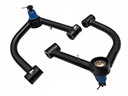 Chevrolet Metro Control Arm
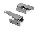 Chevrolet Metro Control Arm Bracket
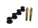 Chevrolet Metro Crossmember Bushing
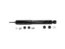 Chevrolet Metro Shock Absorber
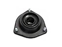 Chevrolet Metro Shock And Strut Mount
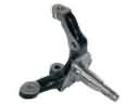 Chevrolet Metro Spindle
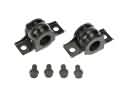 Chevrolet Metro Sway Bar Bracket
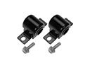 Chevrolet Metro Sway Bar Bushing
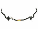 Chevrolet Metro Sway Bar Kit
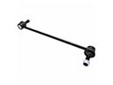 Chevrolet Metro Sway Bar Link
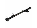 Chevrolet Metro Trailing Arm
 Chevrolet Metro Wheel Seal