ChevyParts
My Garage
My Account
Cart
OEM Chevrolet Blazer Fuel Injector
Gas Injector- Select Vehicle by Model
- Select Vehicle by VIN
Select Vehicle by Model
orMake
Model
Year
Select Vehicle by VIN
For the most accurate results, select vehicle by your VIN (Vehicle Identification Number).
13 Fuel Injectors found

Chevrolet Blazer Injector Part Number: 88894353
$120.24 MSRP: $244.20You Save: $123.96 (51%)Ships in 1-2 Business Days
Chevrolet Blazer Injector Part Number: 17111774
$229.73 MSRP: $412.08You Save: $182.35 (45%)Ships in 1-3 Business Days


Chevrolet Blazer Injector Part Number: 19110538
$229.73 MSRP: $412.08You Save: $182.35 (45%)


Chevrolet Blazer Injection Nozzle Part Number: 10233973
Chevrolet Blazer Throttle Body Part Number: 17112511
Chevrolet Blazer Injector Part Number: 17091432

Chevrolet Blazer Injection Nozzle Part Number: 14063606

Chevrolet Blazer Injection Nozzle Part Number: 14059057

Chevrolet Blazer Throttle Body Part Number: 17113673
Chevrolet Blazer Throttle Body Part Number: 17112917
Chevrolet Blazer Throttle Body Part Number: 17112514
Chevrolet Blazer Throttle Body Part Number: 17112508
Chevrolet Blazer Throttle Body Part Number: 17112913
Chevrolet Blazer Fuel Injector
Want to cut long-term maintenance and repair costs? Choose OEM Fuel Injector. Those parts deliver top durability you can trust. On our site, you'll find a huge catalog of genuine Chevrolet Blazer parts. Prices are unbeatable, so you can keep more in your pocket. Every OEM Chevrolet Blazer Fuel Injector includes a manufacturer's warranty. You can also get an easy return policy that keeps buying risk free. Fast delivery, get your car on the road quickly. It's simple to search, compare, and order. Stop guessing about quality or fit. Order today and save with parts that last.
The Fuel Injector is among the critical components of the Chevrolet Blazer series, which is tasked with the responsibility of injecting fuel into the engine's cylinders. This component is a part of the vehicle's ECM, and job of this unit is highly accurate regulation of the injection process depends on the load of the engine, that provides both improve the efficiency and safety of a vehicle. For the Chevrolet Blazer, all manners of fuel injection systems such as direct and indirect modes have been adopted over the years to suit driving varieties. Further, these systems whether multi-point or single-point, aim at obtaining maximum power output for minimal emissions and of course, for the Fuel Injector to preserve the vehicle's standard performance. Maintaining compatibility with multiple Blazer models allows drivers to benefit from this relient fuel injector for use in various engine types such as the 2.0 L turbo and the 3.6 L V6. The Fuel Injector can also be said to boast of the innovative Engineering, which makes it to be able to move and maneuver hence gaining a competitive edge in the automobiles market. Some of the qualities of the Fuel Injector include accurate fuel delivery and the boosting of better charcoal combustion in the Chevrolet Blazer not only makes it a functional booster in performance but also forms a significant part of any Chevrolet Blazer if the owner is looking to gain reliability and quality on the road.
Chevrolet Blazer Fuel Injector Parts and Q&A
- Q: How to clean the fuel injector on Chevrolet Blazer?A:A proper Fuel Injector cleaning procedure should start by clearing Fuel Tank vapor pressure through fuel fill cap loosening. The maintenance sequence starts with taking out the positive crankcase ventilation (PCV) clean air tube from the air inlet duct before setting it aside and then proceeding to remove the resonator and air inlet duct from the Throttle Body. The Brake Booster Vacuum Hose and connector needs detachment from the Intake Manifold before you remove the electrical connector from the central sequential fuel injection (CSFI) fuel metering body. Pennant jet removes Spark Plug Wires from Distributor Cap cylinders 1, 3, 5 while extracting the fuel line bolt situated at the Intake Manifold rear. The technician should remove the fuel system pressure and undo both nut and clamp from the fuel pipe and extract the fuel pipes from the metering body. Install j 44466-12 and j 44466-13 to the metering body before tightening them while maintaining correct fuel pipe o-ring positions. The next step involves attaching the j 44466-11 and clamp together with the j 44466-13 to your fuel pipe before tightening them adequately. Secure the j 41413 while closing the tank valve then take out the regulator assembly. First install j 44466-10 to j 41413 tank before linking j 44466-10 hose to j 44466-12 component. Use the metering body electrical connector to connect the j 39021 and j 39021-210 and j 39021-301 while selecting 0.5 amps on the j 39021 amperage switch. Open the tank valve together with the j 44466-10 control to pressurize the system until it reaches a minimum pressure of 150 psi. Activate the j 39021 to fire an injector which will be checked through the pressure gauge drop to confirm proper operation before firing additional injectors. After testing conclude by turning off the j 41413 tank pressure valve while bleeding the pressure at j 44466-10 and replacing the fresh air tube on the pcv. Separate the j 44466-10 from both the j 44466-12 and j 41413 system and then separate the j 39021-301 and j 39021-210 and j 39021 from the metering body. Begin by reconnecting vehicle electrical power to the metering body then install the Brake Booster Vacuum Hose to the Intake Manifold followed by the ignition wire connection to the Distributor Cap. Fasten the resonator and air intake duct onto the Throttle Body keeping the wing nut at hand-tightening torque. Begin by getting the j 38500-a tool for the clean-up procedure. When you have it, close the valve at the bottom of the canister before adding top engine cleaner gm p/n 1050002 (Canadian P/N 992872) into the canister until it reaches the maximum capacity with regular unleaded gasoline remaining. Then install the canister top. Install the j 38500-a on a suitable underhood space while linking its hose to the service port of the j 44466-12 . Open the j 38500-a bottom valve afterward to secure an Air Hose from the top hole for which you should set the regulator to 75 psi before starting. After the canister empties remove shop air supply and depressurize j 38500-a followed by disconnecting it from j 44466-12. Rearrange the sequence to remove the pcv clean air tube, resonator, air inlet duct and ignition wires. The technician should bleed j 44466-12 before removing j 44466-13 and j 44466-12 from the metering body followed by installing j 44466-13 while using the clamp before assembling j 44466-11 onto the fuel pipe. Reinstall the fuel pipe onto the metering body while placing all o-rings and washers along with spacers correctly, after which install the clamp and nuts before tightening them to 3 n.m (27 lb ft). Before installing the fuel pipe bolt apply threadlock gm p/n 12345382 (Canadian P/N 10953489) to its threads then tighten bolt to 6 n.m (53 lb ft). Start by connecting the Brake Booster Vacuum Hose together with the connector then attach the resonator and air inlet duct followed by installing the pcv clean air tube and finally putting the ignition wires onto the Distributor Cap. Add 1-ounce gm p/n 12345104 (Canadian P/N 12345515) port Fuel Injector cleaner to the tank for every gallon of gas present in the Fuel Tank and tell the customer to finish the remaining cleaner when refilling their gas tank. Start the engine while manually securing the Fuel Tank cap. Verify for any fluid leakage from the system. A tech ii scan tool should be used to check powertrain dtc codes while instructing the customer to switch fuel brands after clearing the stored codes with the tool disconnected.

Related Chevrolet Blazer Parts
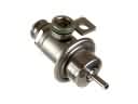 Chevrolet Blazer Fuel Pressure Regulator
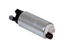 Chevrolet Blazer Fuel Pump
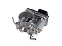 Chevrolet Blazer Throttle Body
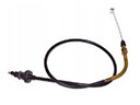 Chevrolet Blazer Accelerator Cable
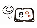 Chevrolet Blazer Carburetor Gasket Kit
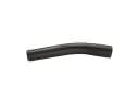 Chevrolet Blazer Fuel Filler Hose
 Chevrolet Blazer Fuel Injector O-Rings
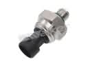 Chevrolet Blazer Fuel Pressure Sensor
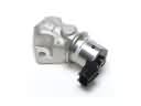 Chevrolet Blazer Idle Control Valve
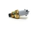 Chevrolet Blazer Intake Manifold Temperature Sensor
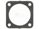 Chevrolet Blazer Throttle Body Gasket
 Chevrolet Blazer Throttle Cable