ChevyParts
My Garage
My Account
Cart
OEM Chevrolet Astro Fuel Injector
Gas Injector- Select Vehicle by Model
- Select Vehicle by VIN
Select Vehicle by Model
orMake
Model
Year
Select Vehicle by VIN
For the most accurate results, select vehicle by your VIN (Vehicle Identification Number).
7 Fuel Injectors found

Chevrolet Astro Injector Part Number: 88894353
$120.24 MSRP: $244.20You Save: $123.96 (51%)Ships in 1-2 Business Days
Chevrolet Astro Injector Part Number: 19110532
$154.07 MSRP: $276.36You Save: $122.29 (45%)Ships in 1-3 Business Days


Chevrolet Astro Injector Part Number: 17111986

Chevrolet Astro Injector Part Number: 19110537
$170.77 MSRP: $306.32You Save: $135.55 (45%)
Chevrolet Astro Injector Part Number: 17091432
Chevrolet Astro Injector Part Number: 17068993

Chevrolet Astro Throttle Body Part Number: 17113673
Chevrolet Astro Fuel Injector
Want to cut long-term maintenance and repair costs? Choose OEM Fuel Injector. Those parts deliver top durability you can trust. On our site, you'll find a huge catalog of genuine Chevrolet Astro parts. Prices are unbeatable, so you can keep more in your pocket. Every OEM Chevrolet Astro Fuel Injector includes a manufacturer's warranty. You can also get an easy return policy that keeps buying risk free. Fast delivery, get your car on the road quickly. It's simple to search, compare, and order. Stop guessing about quality or fit. Order today and save with parts that last.
The Fuel Injector is one of the significant parts of the Chevrolet Astro vehicles that facilitate the direct spraying of fuel into the engine cylinder through the control of the Engine Control Module for the right air/fuel mixture. This system is 'returnless,' with fewer fuel lines, so the chances of it going wrong which can cause performance as well as fuel economy to be affected, are minimized. The different models of fuel injectors that have been available in Astro models include the direct and indirect fuel injection, and each of them has a unique modus operandi as far as the delivery and the synchronization of the fuel is concerned. In conclusion, the Fuel Injector becomes an extensive part of the modifications in the internal combustion engines to improve the efficiency and smooth performances instead of carburetor techniques.
Chevrolet Astro Fuel Injector Parts and Q&A
- Q: How to replace the fuel injector on Chevrolet Astro?A:The Fuel Injector replacement requires fuel meter body assembly removal followed by injector assembly retainer (Injector Retainer) and injector retainer lock nuts (Lock Nuts) elimination. You need to be careful about Fuel Injector removal because the electrical connector terminals and the injector filter along with fuel nozzle form a complete assembly unit. The electric nature of the injectors demands protection from any contact with liquid solvents because these substances can cause enduring damage. A small tip punch should be used to push down between injector terminals when the poppet nozzle tube is pulled downward for injector removal. The installation process requires using flow-rate calibrated injectors according to the specific application service needs. New injector o-ring seals need lubrication with clean engine oil before they can be installed onto the injector assembly. Set the Fuel Injector assembly inside the fuel meter body injector socket before installation. Mount the injector retainer onto the assembly followed by placement of lock nuts then tighten them to 3 n.m (27 lb in). Terminate the operation by installing the fuel meter body assembly.
- Q: How to clean and service the fuel injector on Chevrolet Astro?A:The Fuel Injector service process starts with opening the fuel filler cap to release the Fuel Tank vapor pressure followed by removing the engine cover and resonator with the air inlet duct from the Throttle Body. You should first remove the Brake Booster Vacuum Hose alongside its Intake Manifold connector before taking out the central sequential fuel injection (CSFI) fuel metering body electrical connector. Remove Spark Plug Wires from Distributor Cap on cylinders 1, 3, 5 followed by fuel system pressure relief and fuel pipe disconnection at the rear of the intake. Secure the fuel line bolt while keeping all fuel pipe o-rings, washers and spacers properly positioned before removing nuts and clamp from the fuel pipe. First tighten the j 44466-12 and j 44466-13 installed to the metering body before applying the j 44466-1 to the fuel pipe and re-tightening it. First apply the j 41413 to shut the tank valve and extract the regulator system and obtain the j 44466-10 component from the j 41413 tank. Screw the j 44466-10 hose to the j 44466-12-metering body. Then attach the j 39021 along with its companion j 39021-210, j 39021-301 to the electrical connector. Adjust the j 39021 amperage selector to 0.5 amps before continuing. Open both tank valves along with j 44466-10 and pressurize the fuel system until it reaches at least 150 psi pressure. You should confirm each injector function by using the j 39021 while observing pressure drops. The j 41413 should receive its pressure valve closed before venting pressure from the j 44466-10 and disconnecting the j 44466-12 and j 41413. Disconnect the j 39021-301, j 39021-210, and j 39021 from the metering body after which the vehicle electrical connector can be reinstalled. Installation of the Brake Booster Vacuum Hose and ignition wires must be followed by the resonator and air intake duct. Fit the j 38500-a canister by closing its bottom valve and filling it with regular unleaded gasoline plus the top engine cleaner gm p/n 12346535 product. Use the j 38500-a to suspend it while connecting the hose to the j 44466-12 service port. Then open the canister valve at the bottom before attaching a shop air source at the top fitting by adjusting the regulator to 75 psi. Allow the vehicle to run until the canister empties completely before extracting air supply and depressurizing the j 38500-a. Proceed to detach the hose from the j 44466-12, extract both the resonator and air inlet duct as well as ignition wires. After bleeding residual pressure through the j 44466-12, workers should remove the j 44466-13 and j 44466-12 from the metering body next to then disconnect the j 44466-1 from the fuel lines while making sure all components like o-rings, washers, and spacers stay in their appropriate place. The fuel pipe installation procedure includes attaching it to the metering body using a clamp with nuts and tightening these components to 3 nm (27 lb ft) while applying threadlock gm p/n 12345382 to the fuel pipe bolt prior to installing it to 6 nm (53 lb ft). Perform the installment of the Brake Booster Vacuum Hose and connector and the resonator with accompanying air inlet duct as well as ignition wire connection. The engine cover needs replacement while professionals should add one ounce port Fuel Injector cleaner gn p/n 12345104 (or P/N 12345515 in Canada) into the Fuel Tank for each gallon of gasoline. Tell the customer to use the remaining bottle during its next fuel fill-up and suggest them to switch their fuel brand. After start-up check for leakages while having the Fuel Tank filler cap hand-tightened. Then use a tech ii scan tool to review and clear powertrain diagnostic trouble codes (DTCs) before disconnecting it.

Related Chevrolet Astro Parts
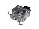 Chevrolet Astro Throttle Body
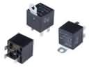 Chevrolet Astro Fuel Pump Relay
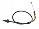 Chevrolet Astro Accelerator Cable
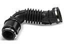 Chevrolet Astro Air Intake Hose
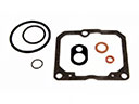 Chevrolet Astro Carburetor Gasket Kit
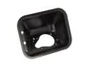 Chevrolet Astro Fuel Filler Housing
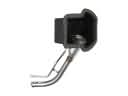 Chevrolet Astro Fuel Filler Neck
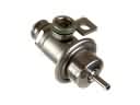 Chevrolet Astro Fuel Pressure Regulator
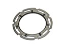 Chevrolet Astro Fuel Tank Lock Ring
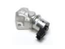 Chevrolet Astro Idle Control Valve
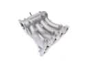 Chevrolet Astro Intake Manifold
 Chevrolet Astro Throttle Body Gasket